Jeep XJ. Manual - part 412


  Index      Jeep     Jeep XJ - service repair manual 2001 year


Search            


Content   ..  410  411  412  413   ..


Jeep XJ. Manual - part 412


(9) Install piston spring in retainer and on top of

piston (Fig. 195). Concave side of spring faces down-
ward (toward piston).

(10) Install wave spring in retainer (Fig. 195). Be

sure spring is completely seated in retainer groove.

(11) Install

bottom

pressure

plate

(Fig.

190).

Ridged side of plate faces downward (toward piston)
and flat side toward clutch pack.

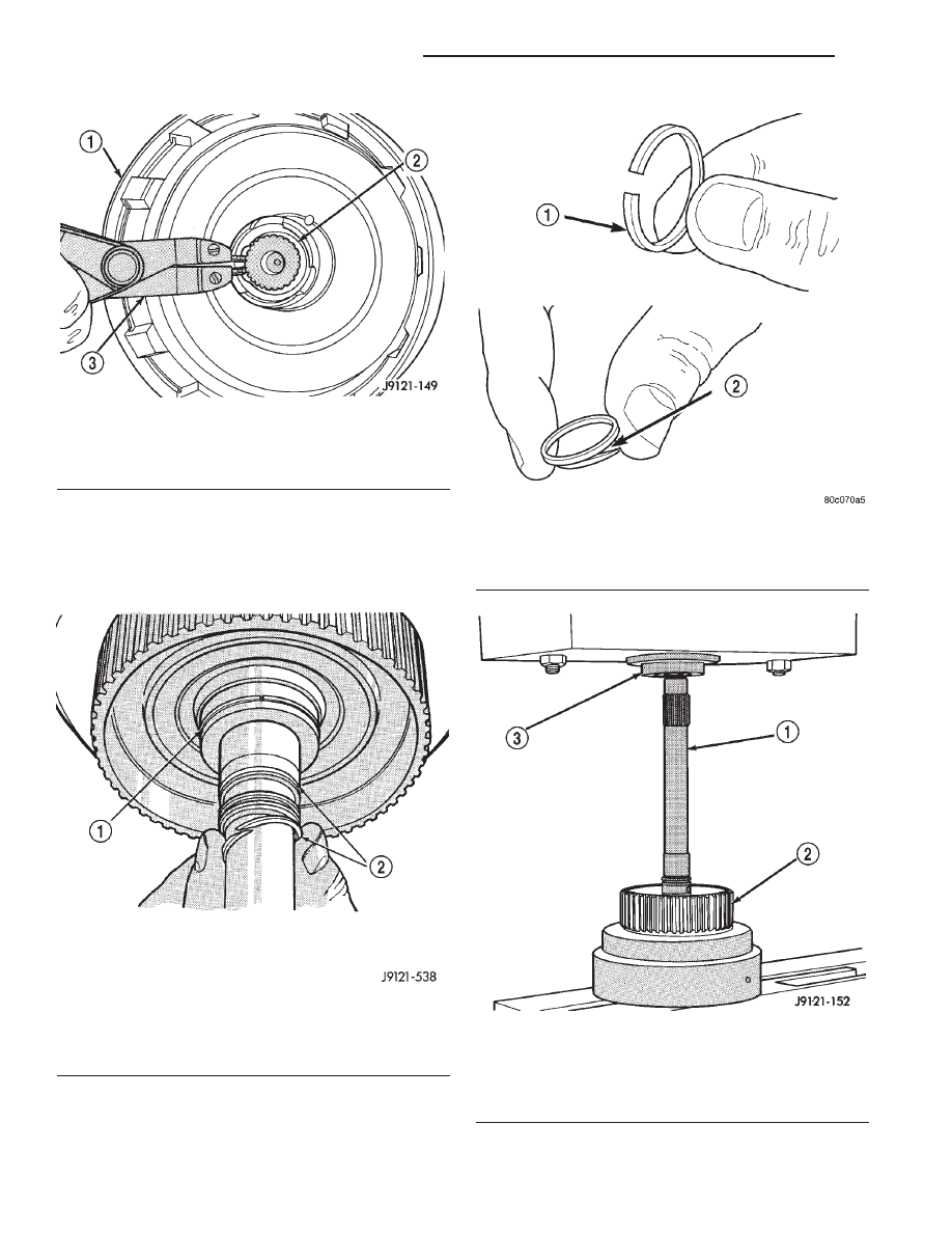
Fig. 191 Removing/Installing Input Shaft Snap-Ring

1 – REAR CLUTCH RETAINER
2 – INPUT SHAFT SNAP RING
3 – SNAP RING PLIERS

Fig. 192 Rear Clutch Retainer And Input Shaft Seal

Ring Installation

1 – REAR CLUTCH RETAINER HUB SEAL RING
2 – INPUT SHAFT SEAL RINGS

Fig. 193 Input Shaft Seal Ring Identification

1 – PLASTIC REAR SEAL RING
2 – TEFLON FRONT SEAL RING (SQUEEZE RING TOGETHER

SLIGHTLY BEFORE INSTALLATION FOR BETTER FIT)

Fig. 194 Pressing Input Shaft Into Rear Clutch

Retainer

1 – INPUT SHAFT
2 – REAR CLUTCH RETAINER
3 – PRESS RAM

21 - 184

AUTOMATIC TRANSMISSION—30RH

XJ

DISASSEMBLY AND ASSEMBLY (Continued)

(12) Install first clutch disc in retainer on top of

bottom pressure plate. Then install a clutch plate fol-
lowed by a clutch disc until entire clutch pack is
installed (4 discs and 3 plates are required) (Fig.
190).

(13) Install top pressure plate.
(14) Install selective snap ring. Be sure snap ring

is fully seated in retainer groove.

(15) Using a suitable gauge bar and dial indicator,

measure clutch pack clearance (Fig. 196).

(a) Position gauge bar across the clutch drum

with the dial indicator pointer on the pressure
plate (Fig. 196).

(b) Using two small screw drivers, lift the pres-

sure plate and release it.

(c) Zero the dial indicator.
(d) Lift the pressure plate until it contacts the

snap-ring and record the dial indicator reading.
Clearance should be 0.64 - 1.14 mm (0.025 - 0.045

in.). If clearance is incorrect, steel plates, discs, selec-
tive snap ring and pressure plates may have to be
changed.

The selective snap ring thicknesses are:
• .107–.109 in.

• .098–.100 in.

• .095–.097 in.

• .083–.085 in.

• .076–.078 in.

• .071–.073 in.

• .060–.062 in.
(16) Coat rear clutch thrust washer with petro-

leum jelly and install washer over input shaft and
into clutch retainer (Fig. 197). Use enough petroleum
jelly to hold washer in place.

PLANETARY GEARTRAIN/OUTPUT SHAFT

DISASSEMBLY

(1) Remove planetary snap ring (Fig. 198).
(2) Remove front annulus and planetary assembly

from driving shell (Fig. 198).

(3) Remove snap ring that retains front planetary

gear in annulus gear (Fig. 199).

(4) Remove tabbed thrust washer and tabbed

thrust plate from hub of front annulus (Fig. 200).

(5) Separate front annulus and planetary gears

(Fig. 200).

Fig. 195 Piston Spring/Wave Spring Position

1 – REAR CLUTCH RETAINER
2 – PISTON SPRING
3 – WAVE SPRING
4 – CLUTCH PISTON

Fig. 196 Checking Rear Clutch Pack Clearance

1 – DIAL INDICATOR
2 – PRESSURE PLATE
3 – SNAP RING
4 – STAND
5 – REAR CLUTCH
6 – GAUGE BAR

Fig. 197 Installing Rear Clutch Thrust Washer

1 – REAR CLUTCH RETAINER
2 – REAR CLUTCH THRUST WASHER

XJ

AUTOMATIC TRANSMISSION—30RH

21 - 185

DISASSEMBLY AND ASSEMBLY (Continued)

(6) Remove

front

planetary

gear

front

thrust

washer from annulus gear hub.

(7) Separate and remove driving shell, rear plane-

tary and rear annulus from output shaft (Fig. 201).

(8) Remove front planetary rear thrust washer

from driving shell.

(9) Remove tabbed thrust washers from rear plan-

etary gear.

(10) Remove lock ring that retains sun gear in

driving shell. Then remove sun gear, spacer and
thrust plates.

ASSEMBLY

(1) Lubricate output shaft and planetary compo-

nents with transmission fluid. Use petroleum jelly to
lubricate and hold thrust washers and plates in posi-
tion.

(2) Assemble rear annulus gear and support if dis-

assembled. Be sure support snap ring is seated and
that shoulder-side of support faces rearward (Fig.
202).

(3) Install rear thrust washer on rear planetary

gear. Use enough petroleum jelly to hold washer in
place. Also be sure all four washer tabs are properly
engaged in gear slots.

(4) Install rear annulus over and onto rear plane-

tary gear (Fig. 202).

(5) Install assembled rear planetary and annulus

gear on output shaft (Fig. 203). Verify that assembly
is fully seated on shaft.

(6) Install front thrust washer on rear planetary

gear (Fig. 204). Use enough petroleum jelly to hold

Fig. 198 Front Annulus And Planetary Assembly

Removal

1 – DRIVING SHELL
2 – FRONT ANNULUS AND PLANETARY ASSEMBLY
3 – PLANETARY SNAP RING

Fig. 199 Front Planetary Snap Ring Removal

1 – FRONT ANNULUS GEAR
2 – PLANETARY SNAP RING

Fig. 200 Front Planetary And Annulus Gear

Disassembly

1 – FRONT ANNULUS
2 – THRUST WASHER
3 – THRUST PLATE
4 – FRONT THRUST WASHER
5 – FRONT PLANETARY

Fig. 201 Removing Driving Shell, Rear Planetary

And Rear Annulus

1 – REAR ANNULUS
2 – REAR PLANETARY
3 – DRIVING SHELL
4 – OUTPUT SHAFT

21 - 186

AUTOMATIC TRANSMISSION—30RH

XJ

DISASSEMBLY AND ASSEMBLY (Continued)

washer on gear. Be sure all four washer tabs are
seated in slots.

(7) Install spacer on sun gear (Fig. 205).
(8) Install thrust plate on sun gear (Fig. 206). Note

that driving shell thrust plates are interchangeable.
Use either plate on sun gear and at front/rear of
shell.

Fig. 202 Assembling Rear Annulus And Planetary

Gear

1 – REAR ANNULUS GEAR
2 – TABBED THRUST WASHER
3 – REAR PLANETARY

Fig. 203 Installing Rear Annulus And Planetary On

Output Shaft

1 – REAR ANNULUS AND PLANETARY GEAR ASSEMBLY
2 – OUTPUT SHAFT

Fig. 204 Installing Rear Planetary Front Thrust

Washer

1 – FRONT TABBED THRUST WASHER
2 – REAR PLANETARY GEAR

Fig. 205 Installing Spacer On Sun Gear

1 – SUN GEAR
2 – SUN GEAR SPACER

XJ

AUTOMATIC TRANSMISSION—30RH

21 - 187

DISASSEMBLY AND ASSEMBLY (Continued)


Content   ..  410  411  412  413   ..