Jeep XJ. Manual - part 410


  Index      Jeep     Jeep XJ - service repair manual 2001 year


Search            


Content   ..  408  409  410  411   ..


Jeep XJ. Manual - part 410


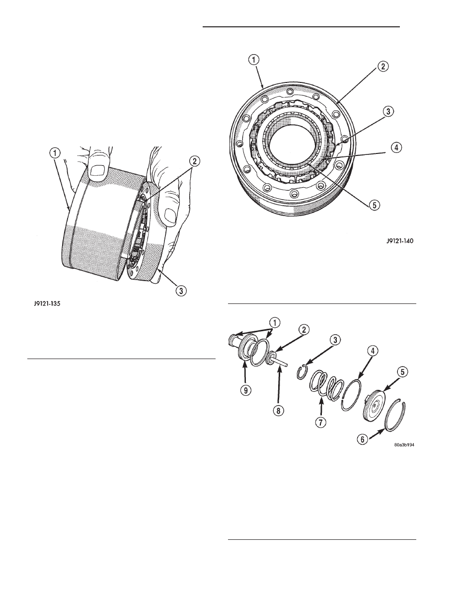
(b) Install clutch assembly on low-reverse drum

with twisting motion (Fig. 167).

(c) Install drum-clutch assembly in case and

install clutch cam bolts.

(d) Install rear support and support attaching

bolts.

(e) Check

low-reverse

drum

rotation.

Drum

should rotate freely in clockwise direction
and lock when turned in counterclockwise
direction (as viewed from front of case).

FRONT SERVO PISTON

DISASSEMBLY

(1) Remove seal ring from rod guide (Fig. 169).
(2) Remove small snap ring from servo piston rod.

Then remove piston rod, spring and washer from pis-
ton.

(3) Remove and discard servo component O-ring

and seal rings.

ASSEMBLY

(1) Lubricate new O-ring and seal rings with

petroleum jelly and install them on piston, guide and
rod.

(2) Install rod in piston. Install spring and washer

on rod. Compress spring and install snap ring (Fig.
169).

(3) Set servo components aside for installation dur-

ing transmission reassembly.

Fig. 167 Temporary Assembly Of Clutch And Drum

To Check Operation

1 – LOW-REVERSE DRUM
2 – CLUTCH RACE (ON HUB OF DRUM)
3 – OVERRUNNING CLUTCH

Fig. 168 Assembled Overrunning Clutch

1 – LOW-REVERSE DRUM
2 – OVERRUNNING CLUTCH CAM
3 – ROLLER AND SPRING ASSEMBLY
4 – CLUTCH RACE
5 – HUB OF LOW-REVERSE DRUM

Fig. 169 Front Servo

1 – PISTON RINGS
2 – O-RING
3 – SNAP-RING
4 – SEAL RING
5 – PISTON ROD GUIDE
6 – SNAP-RING
7 – SERVO SPRING
8 – PISTON ROD
9 – SERVO PISTON

21 - 176

AUTOMATIC TRANSMISSION—30RH

XJ

DISASSEMBLY AND ASSEMBLY (Continued)

REAR SERVO PISTON

DISASSEMBLY

(1) Remove small snap ring and remove plug and

spring from servo piston (Fig. 170).

(2) Remove and discard servo piston seal ring.

ASSEMBLY

(1) Lubricate piston and guide seals with petro-

leum jelly. Lubricate other servo parts with Mopar

t

ATF Plus 3, Type 7176, transmission fluid.

(2) Install new seal ring on servo piston.
(3) Assemble piston, plug, spring and new snap

ring.

(4) Lubricate piston seal lip with petroleum jelly.

OIL PUMP AND REACTION SHAFT SUPPORT

DISASSEMBLY

(1) Remove seal ring from housing and reaction

shaft support (Fig. 171).

(2) Mark pump housing and support assembly for

alignment reference.

(3) Remove bolts attaching pump body to support

(Fig. 172).

(4) Separate support from pump housing (Fig.

173).

(5) Remove inner and outer gears from reaction

shaft support (Fig. 174).

(6) If pump seal was not removed during transmis-

sion disassembly, remove seal with punch and ham-
mer.

(7) Remove front clutch thrust washer from sup-

port hub (Fig. 175).

Fig. 171 Removing Pump Seal Ring

1 – PUMP HOUSING SEAL RING

Fig. 170 Rear Servo Components

1 – SNAP RING
2 – PISTON SEAL
3 – PISTON PLUG
4 – SPRING RETAINER
5 – SNAP RING
6 – PISTON SPRING
7 – CUSHION SPRING
8 – PISTON

Fig. 172 Pump Support Bolts

1 – REACTION SHAFT SUPPORT
2 – PUMP

Fig. 173 Separating Pump Housing From Reaction

Shaft Support

1 – REACTION SHAFT SUPPORT
2 – PUMP HOUSING

XJ

AUTOMATIC TRANSMISSION—30RH

21 - 177

DISASSEMBLY AND ASSEMBLY (Continued)

OIL PUMP BUSHING REPLACEMENT

(1) Remove

pump

bushing

with

Tool

Handle

C-4171 and Bushing Remover SP-3551 from Tool Set
C-3887-J (Fig. 176).

(2) Install new pump bushing with Tool Handle

C-4171 and Bushing Installer SP-5117 (Fig. 176).
Bushing should be flush with pump housing bore.

(3) Stake new pump bushing in two places with

blunt punch (Fig. 177). Remove burrs from stake
points with knife blade afterward.

REACTION SHAFT SUPPORT BUSHING REMOVAL

(1) Assemble Bushing Remover Tools SP-1191,

3633 and 5324 (Fig. 178). Do not clamp any part
of reaction shaft or support in vise.

(2) Hold Cup Tool SP-3633 firmly against reaction

shaft and thread remover SP-5324 into bushing as

far as possible by hand. Then thread remover tool 3-4
additional turns into bushing with a wrench.

(3) Turn remover tool hex nut down against

remover cup to pull bushing from shaft. Clean all
chips from shaft after bushing removal.

Fig. 174 Pump Gear Removal

1 – REACTION SHAFT SUPPORT
2 – INNER GEAR
3 – OUTER GEAR

Fig. 175 Support Hub Thrust Washer

1 – BUSHING
2 – REACTION SHAFT SUPPORT
3 – THRUST WASHER
4 – HUB

Fig. 176 Removing Oil Pump Bushing

1 – SPECIAL TOOL C-4171
2 – SPECIAL TOOL SP-3551
3 – BUSHING
4 – SPECIAL TOOL SP-5117
5 – BUSHING
6 – SPECIAL TOOL C-4171
7 – PUMP HOUSING

Fig. 177 Staking Oil Pump Bushing

1 – NARROW BLADE
2 – BLUNT PUNCH
3 – TWO STAKES

21 - 178

AUTOMATIC TRANSMISSION—30RH

XJ

DISASSEMBLY AND ASSEMBLY (Continued)

(4) Lightly grip old bushing in vise or with pliers

and back remover tool out of bushing.

(5) Assemble Bushing Installer Tools C-4171 and

SP-5325 (Fig. 178).

(6) Slide new bushing onto Installer Tool SP-5325.
(7) Position reaction shaft support upright on a

clean smooth surface.

(8) Align bushing in bore. Then tap bushing into

place until Bushing Installer SP-5325 bottoms.

(9) Clean reaction shaft support thoroughly after

installing bushing.

ASSEMBLY

(1) Lubricate gear bore in pump housing with

transmission fluid.

(2) Lubricate pump gears with transmission fluid.
(3) Support pump housing on wood blocks (Fig.

179).

(4) Install outer gear in pump housing (Fig. 179).

Gear can be installed either way (it is not a one-way
fit).

(5) Install pump inner gear (Fig. 180).

CAUTION: The pump inner gear is a one way fit.
The bore on one side of the gear inside diameter (I.
D.) is chamfered. Be sure the chamfered side faces
forward (to front of pump).

(6) Install new thrust washer on hub of reaction

shaft support. Lubricate washer with transmission
fluid or petroleum jelly.

(7) If reaction shaft seal rings are being replaced,

install new seal rings on support hub (Fig. 181).

Lubricate seal rings with transmission fluid or petro-
leum jelly after installation. Squeeze each ring until
ring ends are securely hooked together.

CAUTION: The reaction shaft support seal rings
will break if overspread, or twisted. If new rings are
being installed, spread them only enough for instal-
lation. Also be very sure the ring ends are securely
hooked together after installation. Otherwise, the
rings will either prevent pump installation, or break
during installation.

(8) Install reaction shaft support on pump housing

(Fig. 182).

(9) Align reaction support on pump housing. Use

alignment marks made at disassembly. Or, rotate
support until bolt holes in support and pump housing
are all aligned (holes are offset for one-way fit).

Fig. 178 Replacing Reaction Shaft Support Bushing

1 – SPECIAL TOOL SP-1191
2 – SPECIAL TOOL SP-3633
3 – SPECIAL TOOL C-4171
4 – SPECIAL TOOL SP-5325
5 – REACTION SHAFT
6 – SPECIAL TOOL SP-5324
7 – BUSHING

Fig. 179 Supporting Pump And Installing Outer Gear

1 – OUTER GEAR
2 – PUMP HOUSING
3 – WOOD BLOCKS

Fig. 180 Pump Inner Gear Installation

1 – OUTER GEAR
2 – INNER GEAR

XJ

AUTOMATIC TRANSMISSION—30RH

21 - 179

DISASSEMBLY AND ASSEMBLY (Continued)


Content   ..  408  409  410  411   ..