Jeep XJ. Manual - part 302


  Index      Jeep     Jeep XJ - service repair manual 2001 year


Search            


Content   ..  300  301  302  303   ..


Jeep XJ. Manual - part 302


VALVE SEAT REFACING

(1) Install a pilot of the correct size in the valve

guide bore. Reface the valve seat to the specified
angle with a good dressing stone. Remove only
enough metal to provide a smooth finish.

(2) Use tapered stones to obtain the specified seat

width when required.

(3) Control valve seat runout to a maximum of

0.0635 mm (0.0025 in.) (Fig. 15).

VALVE STEM OIL SEAL REPLACEMENT

Valve stem oil seals are installed on each valve

stem to prevent rocker arm lubricating oil from
entering the combustion chamber through the valve
guide bores. One seal is marked INT (intake valve)
and the other is marked EXH (exhaust valve).

Replace the oil seals whenever valve service is per-

formed or if the seals have deteriorated.

VALVE GUIDES

The valve guides are an integral part of the engine

cylinder head and are not replaceable.

When the valve stem guide clearance is excessive,

the valve guide bores must be reamed oversize. Ser-
vice valves with oversize stems are available in 0.076
mm (0.003 inch) and 0.381 mm (0.015 inch) incre-
ments.

Corresponding oversize valve stem seals are also

available and must be used with valves having 0.381
mm (0.015 inch) oversize stems.

NOTE: If the valve guides are reamed oversize, the
valve seats must be ground to ensure that the valve
seat is concentric to the valve guide.

VALVE STEM-TO-GUIDE CLEARANCE
MEASUREMENT

Valve stem-to-guide clearance may be measured by

either of the following two methods.

PREFERRED METHOD

(1) Remove the valve from the head.
(2) Clean the valve stem guide bore with solvent

and a bristle brush.

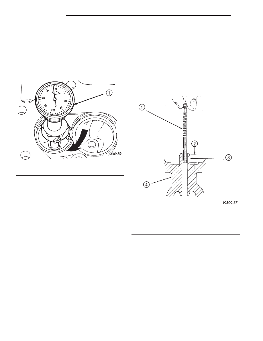
(3) Insert a telescoping gauge into the valve stem

guide bore approximately 9.525 mm (.375 inch) from
the valve spring side of the head (Fig. 16).

(4) Remove and measure telescoping gauge with a

micrometer.

(5) Repeat the measurement with contacts length-

wise to engine cylinder head.

(6) Compare the crosswise to lengthwise measure-

ments to determine out-of-roundness. If the measure-
ments differ by more than 0.0635 mm (0.0025 in.),
ream the guide bore to accommodate an oversize
valve stem.

(7) Compare the measured valve guide bore diam-

eter with specifications (7.95-7.97 mm or 0.313-0.314
inch). If the measurement differs from specification
by more than 0.076 mm (0.003 inch), ream the guide
bore to accommodate an oversize valve stem.

Fig. 15 Measurement of Valve Seat Runout

1 – DIAL INDICATOR

Fig. 16 Measurement of Valve Guide Bore Diameter

1 – GAUGE
2 – 9.525 MM (3/8 INCH)
3 – VALVE STEM GUIDE
4 – CYLINDER HEAD

9 - 76

4.0L ENGINE

XJ

SERVICE PROCEDURES (Continued)

ALTERNATIVE METHOD

(1) Use a dial indicator to measure the lateral

movement of the valve stem (stem-to-guide clear-
ance). This must be done with the valve installed in
its guide and just off the valve seat (Fig. 17).

(2) Correct

clearance

is

0.025-0.0762

mm

(0.001-0.003 inch). If indicated movement exceeds the
specification ream the valve guide to accommodate
an oversize valve stem.

NOTE: Valve seats must be ground after reaming
the valve guides to ensure that the valve seat is
concentric to the valve guide.

VALVE SPRING TENSION TEST

Use a universal Valve Spring Tester and a torque

wrench to test each valve spring for the specified ten-
sion value (Fig. 18).

Replace valve springs that are not within specifica-

tions.

PISTON FITTING

BORE GAGE METHOD

(1) To correctly select the proper size piston, a cyl-

inder bore gauge, capable of reading in 0.003 mm
(.0001 in.) INCREMENTS is required. If a bore
gauge is not available, do not use an inside microme-
ter.

(2) Measure the inside diameter of the cylinder

bore at a point 49.5 mm (1-15/16 inches) below top of
bore. Start perpendicular (across or at 90 degrees) to
the axis of the crankshaft at point A and then take
an additional bore reading 90 degrees to that at point
B (Fig. 20).

(3) The coated pistons will be serviced with the

piston pin and connecting rod pre-assembled. The

coated piston connecting rod assembly can be
used to service previous built engines and
MUST be replaced as complete sets. 
Tin coated
pistons should not be used as replacements for coated
pistons.

(4) The coating material is applied to the piston

after the final piston machining process. Measuring
the outside diameter of a coated piston will not pro-
vide accurate results (Fig. 19). Therefore measuring
the inside diameter of the cylinder bore with a dial
Bore Gauge is MANDATORY. To correctly select the
proper size piston, a cylinder bore gauge capable of
reading in 0.003 mm (.0001 in.) increments is
required.

(5) Piston

installation

into

the

cylinder

bore

requires slightly more pressure than that required
for non-coated pistons. The bonded coating on the
piston will give the appearance of a line-to-line fit
with the cylinder bore.

PISTON RING—FITTING

(1) Carefully

clean

the

carbon

from

all

ring

grooves. Oil drain openings in the oil ring groove and
pin boss must be clear. DO NOT remove metal from
the grooves or lands. This will change ring-to-groove
clearances and will damage the ring-to-land seating.

(2) Be sure the piston ring grooves are free of

nicks and burrs.

(3) Measure the ring side clearance with a feeler

gauge fitted snugly between the ring land and ring
(Fig. 21) (Fig. 22). Rotate the ring in the groove. It
must move freely around circumference of the groove.

(4) Place ring in the cylinder bore and push down

with inverted piston to position near lower end of the
ring travel. Measure ring gap with a feeler gauge fit-
ting snugly between ring ends (Fig. 23).

Fig. 17 Measurement of Lateral Movement of Valve

Stem

1 – DIAL INDICATOR

Fig. 18 Valve Spring Tester

1 – TORQUE WRENCH
2 – VALVE SPRING TESTER

XJ

4.0L ENGINE

9 - 77

SERVICE PROCEDURES (Continued)

(5) The oil control rings are symmetrical, and can

be installed with either side up. It is not necessary to
use a tool to install the upper and lower rails. Insert
oil rail spacer first, then side rails.

(6) The two compression rings are different and

cannot be interchanged. The top compression ring
can be identified by the shiny coating on the outer
sealing surface and can be installed with either side
up. (Fig. 24).

Fig. 19 Moly Coated Piston

1 – MOLY COATED
2 – MOLY COATED

Fig. 20 Bore Gauge

1 – FRONT
2 – BORE GAUGE
3 – CYLINDER BORE
4 – 49.5 MM (1–15/16 in)

PISTON SIZE CHART

CYLINDER BORE SIZE

PISTON LETTER SIZE

98.438 - 98.448 mm

(3.8755 - 3.8759 in.)

A

98.448 - 98.458 mm

(3.8759 - 3.8763 in.)

B

98.458 - 98.468 mm

(3.8763 - 3.8767 in.)

C

98.468 - 98.478 mm

(3.8767 - 3.8771 in.)

D

98.478 - 98.488 mm

(3.8771 - 3.8775 in.)

E

98.488 - 98.498 mm

(3.8775 - 3.8779 in.)

F

Fig. 21 Piston Dimensions

9 - 78

4.0L ENGINE

XJ

SERVICE PROCEDURES (Continued)

(7) The second compression ring has a slight

chamfer on the bottom of the inside edge and a dot
on the top for correct installation (Fig. 25).

(8) Using a ring installer, install the second com-

pression ring with the dot facing up (Fig. 25) (Fig.
27).

(9) Using a ring installer, install the top compres-

sion ring (either side up).

Ring Gap Orientation

• Position the gaps on the piston as shown (Fig.

28).

• Oil spacer - Gap on center line of piston skirt.

• Oil rails - gap 180° apart on centerline of piston

pin bore.

• No. 2 Compression ring - Gap 180° from top oil

rail gap.

• No. 1 Compression ring - Gap 180° from No. 2

compression ring gap.

Fig. 22 Ring Side Clearance Measurement

1 – FEELER GAUGE

RING SIDE CLEARANCE CHART

ITEM

SPECIFICATION

Top Compression Ring

0.042 - 0.084 mm

(0.0017 - 0.0033 in.)

Second Compression

Ring

0.042 - 0.084 mm

(0.0017 - 0.0033 in.)

Oil Control Ring

0.06 - 0.21 mm

(0.0024 - 0.0083 in.)

Fig. 23 Gap Measurement

1 – FEELER GAUGE

RING GAP MEASUREMENT CHART

ITEM

SPECIFICATION

Top Compression Ring

0.229 - 0.610 mm

(0.0090 - 0.0240 in.)

Second Compression

Ring

0.483 - 0.965 mm

(0.0190 - 0.080 in.)

Oil Control Ring

0.254 - 1.500 mm

(0.010 - 0.060 in.)

Fig. 24 Top Compression ring identification

1 – TOP COMPRESSION RING

XJ

4.0L ENGINE

9 - 79

SERVICE PROCEDURES (Continued)


Content   ..  300  301  302  303   ..