Jeep XJ. Manual - part 47


  Index      Jeep     Jeep XJ - service repair manual 2001 year


Search            


Content   ..  45  46  47  48   ..


Jeep XJ. Manual - part 47


FRONT DISC BRAKES

DESCRIPTION

The calipers are a single piston type. The calipers

are free to slide laterally, this allows continuous com-
pensation for lining wear.

OPERATION

When the brakes are applied fluid pressure is

exerted against the caliper piston. The fluid pressure
is exerted equally and in all directions. This means

pressure exerted against the caliper piston and
within the caliper bore will be equal (Fig. 2).

Fluid pressure applied to the piston is transmitted

directly to the inboard brake shoe. This forces the
shoe lining against the inner surface of the disc
brake rotor. At the same time, fluid pressure within
the piston bore forces the caliper to slide inward on
the mounting bolts. This action brings the outboard
brake shoe lining into contact with the outer surface
of the disc brake rotor.

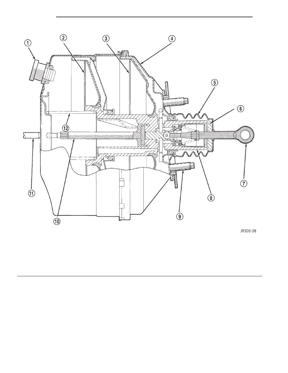
Fig. 1 Power Brake Booster–Typical

1 – VACUUM CHECK VALVE
2 – FRONT DIAPHRAGM
3 – REAR DIAPHRAGM
4 – HOUSING
5 – SEAL
6 – AIR FILTER

7 – PRIMARY PUSH ROD (TO BRAKE PEDAL)
8 – ATMOSPHERIC INLET VALVE ASSEMBLY
9 – BOOSTER MOUNTING STUDS (4)
10 – SECONDARY PUSH ROD (TO MASTER CYLINDER)
11 – MASTER CYLINDER MOUNTING STUD (2)
12 – SPRING

5 - 4

BRAKES

XJ

DESCRIPTION AND OPERATION (Continued)

In summary, fluid pressure acting simultaneously

on both piston and caliper, produces a strong clamp-
ing action. When sufficient force is applied, friction
will attempt to stop the rotors from turning and
bring the vehicle to a stop.

Application and release of the brake pedal gener-

ates only a very slight movement of the caliper and
piston. Upon release of the pedal, the caliper and pis-
ton return to a rest position. The brake shoes do not
retract an appreciable distance from the rotor. In
fact, clearance is usually at, or close to zero. The rea-
sons for this are to keep road debris from getting
between the rotor and lining and in wiping the rotor
surface clear each revolution.

The caliper piston seal controls the amount of pis-

ton extension needed to compensate for normal lining
wear.

During brake application, the seal is deflected out-

ward by fluid pressure and piston movement (Fig. 3).
When the brakes (and fluid pressure) are released,
the seal relaxes and retracts the piston.

The amount of piston retraction is determined by

the amount of seal deflection. Generally the amount
is just enough to maintain contact between the pis-
ton and inboard brake shoe.

REAR DRUM BRAKE

DESCRIPTION

The rear brakes use a leading shoe (primary) and

trailing shoe (secondary) design (Fig. 4).

OPERATION

When the brake pedal is depressed hydraulic pres-

sure pushes the rear brake wheel cylinder pistons
outward. The wheel cylinder push rods then push the
brake shoes outward against the brake drum. When
the brake pedal is released return springs attached
to the brake shoes pull the shoes back to there orig-
inal position.

PARKING BRAKE

DESCRIPTION

The parking bake is a hand lever and cable oper-

ated system used to apply the rear brakes.

OPERATION

A hand operated lever in the passenger compart-

ment is the main application device. The front cable
is connected between the hand lever and the ten-
sioner. The tensioner rod is attached to the equalizer
which is the connecting point for the rear cables (Fig.
5).

The rear cables are connected to the actuating

lever on each secondary brake shoe. The levers are
attached to the brake shoes by a pin either pressed
into, or welded to the lever. A clip is used to secure
the pin in the brake shoe. The pin allows each lever
to pivot independently of the brake shoe.

To apply the parking brakes, the hand lever is

pulled upward. This pulls the rear brake shoe actu-

Fig. 2 Brake Caliper Operation

1 – CALIPER
2 – PISTON
3 – PISTON BORE
4 – SEAL
5 – INBOARD SHOE
6 – OUTBOARD SHOE

Fig. 3 Lining Wear Compensation By Piston Seal

1 – PISTON
2 – CYLINDER BORE
3 – PISTON SEAL BRAKE PRESSURE OFF
4 – CALIPER HOUSING
5 – DUST BOOT
6 – PISTON SEAL BRAKE PRESSURE ON

XJ

BRAKES

5 - 5

DESCRIPTION AND OPERATION (Continued)

ating levers forward, by means tensioner and cables.
As the actuating lever is pulled forward, the parking
brake strut (which is connected to both shoes), exerts
a linear force against the primary brake shoe. This
action presses the primary shoe into contact with the
drum. Once the primary shoe contacts the drum,
force is exerted through the strut. This force is trans-
ferred through the strut to the secondary brake shoe
causing it to pivot into the drum as well.

A gear type ratcheting mechanism is used to hold

the lever in an applied position. Parking brake
release is accomplished by the hand lever release
button.

A parking brake switch is mounted on the parking

brake lever and is actuated by movement of the
lever. The switch, which is in circuit with the red
warning light in the dash, will illuminate the warn-
ing light whenever the parking brakes are applied.

Parking brake adjustment is controlled by a cable

tensioner mechanism. The cable tensioner, once
adjusted at the factory, should not need further
adjustment under normal circumstances. Adjustment

Fig. 4 Brake Components

1 – ADJUSTER LEVER
2 – ADJUSTER CABLE
3 – HOLDDOWN SPRING AND RETAINERS
4 – ADJUSTER LEVER SPRING
5 – TRAILING SHOE
6 – CYLINDER-TO-SUPPORT SEAL
7 – HOLDDOWN PINS
8 – ACCESS PLUGS
9 – SUPPORT PLATE
10 – CABLE HOLE PLUG

11 – PARK BRAKE STRUT AND SPRING
12 – ADJUSTER SCREW ASSEMBLY
13 – HOLDDOWN SPRING AND RETAINERS
14 – LEADING SHOE
15 – CABLE GUIDE
16 – SHOE RETURN SPRINGS
17 – SHOE GUIDE PLATE
18 – PIN
19 – SHOE SPRING
20 – PARK BRAKE LEVER

Fig. 5 Parking Brake Components

1 – REAR CABLES
2 – EQUALIZER
3 – FRONT CABLE
4 – TENSIONER ROD

5 - 6

BRAKES

XJ

DESCRIPTION AND OPERATION (Continued)

may be required if a new tensioner, or cables are
installed, or disconnected.

BRAKE HOSES AND LINES

DESCRIPTION

Flexible rubber hose is used at both front brakes

and at the rear axle junction block. Double walled
steel tubing is used to connect the master cylinder to
the major hydraulic braking components and then to
the flexible rubber hoses. Double inverted style and
ISO style flares are used on the brake lines.

DIAGNOSIS AND TESTING

BASE BRAKE SYSTEM

Base brake components consist of the brake shoes,

calipers, wheel cylinders, brake drums, rotors, brake
lines, master cylinder, booster, and parking brake
components.

Brake diagnosis involves determining if the prob-

lem is related to a mechanical, hydraulic, or vacuum
operated component.

The first diagnosis step is the preliminary check.

PRELIMINARY BRAKE CHECK

(1) Check condition of tires and wheels. Damaged

wheels and worn, damaged, or underinflated tires
can cause pull, shudder, vibration, and a condition
similar to grab.

(2) If complaint was based on noise when braking,

check suspension components. Jounce front and rear
of vehicle and listen for noise that might be caused
by loose, worn or damaged suspension or steering
components.

(3) Inspect brake fluid level and condition. Note

that the brake reservoir fluid level will decrease in
proportion to normal lining wear. Also note that
brake fluid tends to darken over time. This is
normal and should not be mistaken for contam-
ination.

(a) If fluid level is abnormally low, look for evi-

dence of leaks at calipers, wheel cylinders, brake
lines, and master cylinder.

(b) If fluid appears contaminated, drain out a

sample to examine. System will have to be flushed
if fluid is separated into layers, or contains a sub-
stance other than brake fluid. The system seals
and cups will also have to be replaced after flush-
ing. Use clean brake fluid to flush the system.
(4) Check parking brake operation. Verify free

movement and full release of cables and pedal. Also
note if vehicle was being operated with parking
brake partially applied.

(5) Check brake pedal operation. Verify that pedal

does not bind and has adequate free play. If pedal
lacks free play, check pedal and power booster for
being loose or for bind condition. Do not road test
until condition is corrected.

(6) Check booster vacuum check valve and hose.
(7) If components checked appear OK, road test

the vehicle.

ROAD TESTING

(1) If complaint involved low brake pedal, pump

pedal and note if it comes back up to normal height.

(2) Check brake pedal response with transmission

in Neutral and engine running. Pedal should remain
firm under constant foot pressure.

(3) During road test, make normal and firm brake

stops in 25-40 mph range. Note faulty brake opera-
tion such as low pedal, hard pedal, fade, pedal pulsa-
tion, pull, grab, drag, noise, etc.

(4) Attempt to stop the vehicle with the parking

brake only and note grab, drag, noise, etc.

PEDAL FALLS AWAY

A brake pedal that falls away under steady foot

pressure is generally the result of a system leak. The
leak point could be at a brake line, fitting, hose, or
caliper/wheel cylinder. If leakage is severe, fluid will
be evident at or around the leaking component.

Internal leakage (seal by-pass) in the master cylin-

der caused by worn or damaged piston cups, may
also be the problem cause.

An internal leak in the ABS or RWAL system may

also be the problem with no physical evidence.

LOW PEDAL

If a low pedal is experienced, pump the pedal sev-

eral times. If the pedal comes back up worn linings,
rotors, drums, or rear brakes out of adjustment are
the most likely causes. The proper course of action is
to inspect and replace all worn component and make
the proper adjustments.

SPONGY PEDAL

A spongy pedal is most often caused by air in the

system. However, thin brake drums or substandard
brake lines and hoses can also cause a spongy pedal.
The proper course of action is to bleed the system,
and replace thin drums and substandard quality
brake hoses if suspected.

HARD PEDAL OR HIGH PEDAL EFFORT

A hard pedal or high pedal effort may be due to

lining that is water soaked, contaminated, glazed, or
badly worn. The power booster or check valve could
also be faulty.

XJ

BRAKES

5 - 7

DESCRIPTION AND OPERATION (Continued)


Content   ..  45  46  47  48   ..