Jeep XJ. Manual - part 46
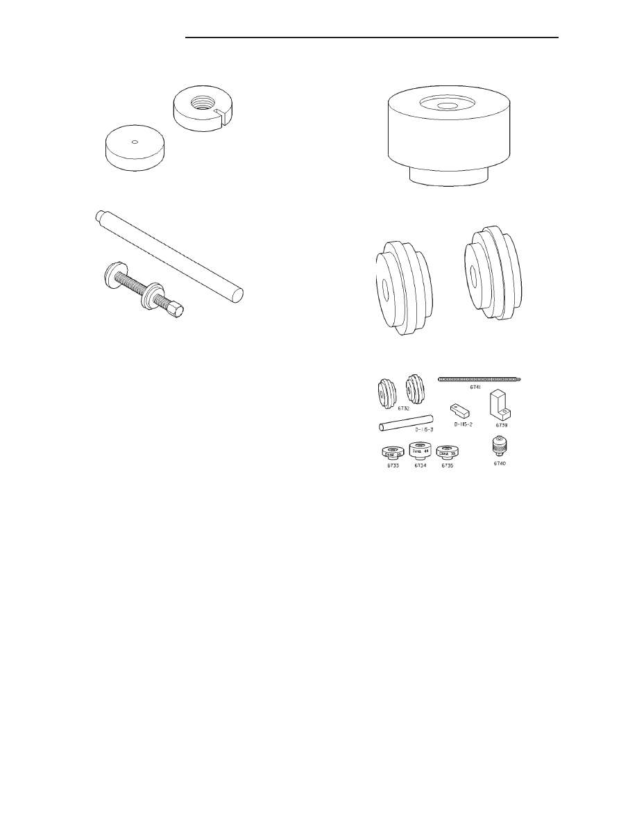
Trac-lok
Y
Tools—8140
Trac-lok
Y
Tools—6960
Pinion Gauge Block—8540
Arbor Discs—8541
Pinion Gauge Set
3 - 134
8 1/4 REAR AXLE
XJ
SPECIAL TOOLS (Continued)
|
|
|
Trac-lok Y Tools—8140 Trac-lok Y Tools—6960 Pinion Gauge Block—8540 Arbor Discs—8541 Pinion Gauge Set 3 - 134 8 1/4 REAR AXLE XJ SPECIAL TOOLS (Continued) |