Jeep XJ. Manual - part 27


  Index      Jeep     Jeep XJ - service repair manual 2001 year


Search            


Content   ..  25  26  27  28   ..


Jeep XJ. Manual - part 27


shims to compress, or preload the new bearings when
the differential is installed.

(15) Rotate dial indicator out of the way on the

guide stud.

(16) Remove differential case and dummy bearings

from axle housing.

(17) Install the pinion in the axle housing. Install

the pinion yoke and establish the correct pinion
rotating torque.

(18) Install differential case and dummy bearings

D-348 in axle housing (without shims), install bear-
ing caps and tighten bolts snug.

(19) Seat ring gear side dummy bearing (Fig. 97).
(20) Position the dial indicator plunger on a flat

surface between the ring gear bolt heads. (Fig. 98).

(21) Push and hold differential case toward pinion

gear (Fig. 101).

(22) Zero dial indicator face to pointer (Fig. 101).

(23) Push and hold differential case to ring gear

side of the axle housing (Fig. 102).

(24) Record dial indicator reading (Fig. 102).

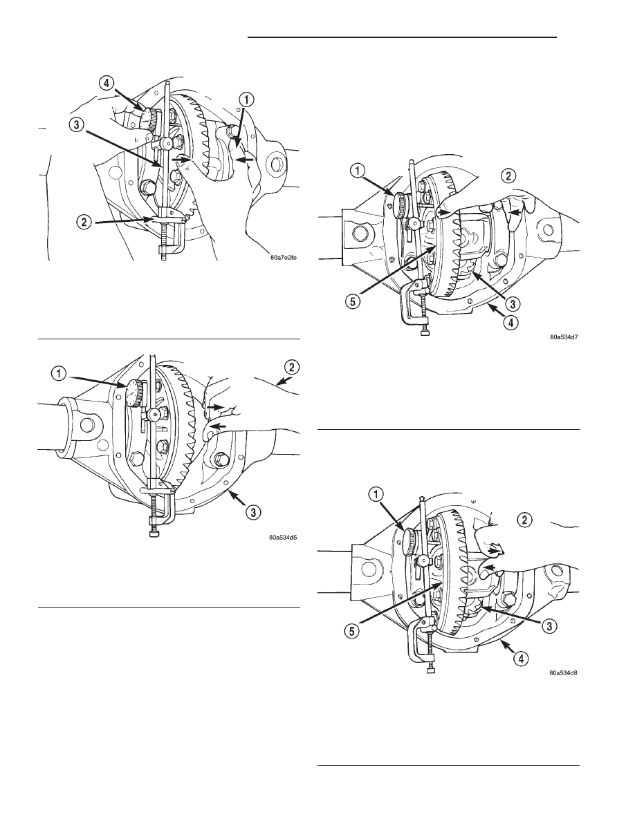
Fig. 99 Hold Differential Case and Zero Dial

Indicator

1 – FORCE DIFFERENTIAL CASE TO PINION GEAR SIDE
2 – SPECIAL TOOL C-3288–B
3 – SPECIAL TOOL C-3339
4 – ZERO DIAL INDICATOR FACE

Fig. 100 Hold Differential Case and Read Dial

Indicator

1 – READ DIAL INDICATOR
2 – FORCE DIFFERENTIAL CASE TO RING GEAR SIDE
3 – AXLE HOUSING

Fig. 101 Hold Differential Case and Zero Dial

Indicator

1 – ZERO DIAL INDICATOR FACE
2 – FORCE DIFFERENTIAL CASE TO PINION GEAR SIDE
3 – PINION GEAR
4 – AXLE HOUSING
5 – DIFFERENTIAL CASE

Fig. 102 Hold Differential Case and Read Dial

Indicator

1 – READ DIAL INDICATOR
2 – FORCE DIFFERENTIAL CASE TO RING GEAR SIDE
3 – PINION GEAR
4 – AXLE HOUSING
5 – DIFFERENTIAL CASE

3 - 58

TUBE, 181, AND 186 FBI AXLE

XJ

ADJUSTMENTS (Continued)

(25) Subtract 0.002 in. (0.05 mm) from the dial

indicator reading to compensate for backlash between
ring and pinion gears. This total is the thickness
shim required to achieve proper backlash.

(26) Subtract the backlash shim thickness from

the total preload shim thickness. The remainder is
the shim thickness required on the pinion side of the
axle housing.

(27) Rotate dial indicator out of the way on guide

stud.

(28) Remove differential case and dummy bearings

from axle housing.

(29) Install side bearing shims on differential case

hubs.

(30) Install side bearings and cups on differential

case.

(31) Install spreader W-129-B, utilizing some items

from Adapter Set 6987, on axle housing and spread
axle opening enough to receive differential case.

(32) Install differential case in axle housing.
(33) Remove spreader from axle housing.
(34) Rotate the differential case several times to

seat the side bearings.

(35) Position the indicator plunger against a ring

gear tooth (Fig. 103).

(36) Push and hold ring gear upward while not

allowing the pinion gear to rotate.

(37) Zero dial indicator face to pointer.
(38) Push and hold ring gear downward while not

allowing the pinion gear to rotate. Dial indicator
reading should be between 0.12 mm (0.005 in.) and
0.20 mm (0.008 in.). If backlash is not within specifi-
cations transfer the necessary amount of shim thick-
ness from one side of the axle housing to the other
(Fig. 104).

(39) Verify differential case and ring gear runout

by measuring ring to pinion gear backlash at eight
locations around the ring gear. Readings should not
vary more than 0.05 mm (0.002 in.). If readings vary
more than specified, the ring gear or the differential
case is defective.

After the proper backlash is achieved, perform

Gear Contact Pattern Analysis procedure.

GEAR CONTACT PATTERN ANALYSIS

The ring gear and pinion teeth contact patterns

will show if the pinion depth is correct in the axle
housing. It will also show if the ring gear backlash
has been adjusted correctly. The backlash can be
adjusted within specifications to achieve desired
tooth contact patterns.

(1) Apply a thin coat of hydrated ferric oxide, or

equivalent, to the drive and coast side of the ring
gear teeth.

(2) Wrap, twist, and hold a shop towel around the

pinion yoke to increase the turning resistance of the

pinion. This will provide a more distinct contact pat-
tern.

(3) Using a boxed end wrench on a ring gear bolt,

Rotate the differential case one complete revolution
in both directions while a load is being applied from
shop towel.

The areas on the ring gear teeth with the greatest

degree of contact against the pinion teeth will squee-
gee the compound to the areas with the least amount
of contact. Note and compare patterns on the ring
gear teeth to Gear Tooth Contact Patterns chart (Fig.
105) and adjust pinion depth and gear backlash as
necessary.

Fig. 103 Ring Gear Backlash Measurement

1 – DIAL INDICATOR

Fig. 104 Backlash Shim Adjustment

XJ

TUBE, 181, AND 186 FBI AXLE

3 - 59

ADJUSTMENTS (Continued)

Fig. 105 Gear Tooth Contact Patterns

3 - 60

TUBE, 181, AND 186 FBI AXLE

XJ

ADJUSTMENTS (Continued)

SPECIFICATIONS

181 FBI AXLE

Axle Type . . . . . . . . . . . . . . . . . . . . . . . . . . Hypoid
Lubricant–Std. . . . . SAE Thermally Stable 80W–90
Lubricant–Heavy Duty . . . SAE 75W–140 Synthetic
Lube Capacity . . . . . . . . . . . . . . . 1.48 L (3.13 pts.)
Axle Ratio . . . . . . . . . . . . . . . . 3.07, 3.55, 3.73, 4.10
Differential Side Gear Clearance . . . 0.12–0.20 mm

(0.005–0.008 in.)

Ring Gear Diameter . . . . . . . . . 18.09 cm (7.125 in.)
Backlash . . . . . . . . . . . 0–0.15 mm (0.005–0.008 in.)
Pinion Std. Depth . . . . . . . . . . . 92.1 mm (3.625 in.)
Pinion Bearing Rotating Torque . . . . . . . . . . . . . . .
Original Bearings . . . . . . . 1–2 N·m (10–20 in. lbs.)
New Bearings . . . . . . . . . 1.5–4 N·m (15–35 in. lbs.)

186 FBI AXLE

Axle Type . . . . . . . . . . . . . . . . . . . . . . . . . . Hypoid
Lubricant–Std. . . . . SAE Thermally Stable 80W–90
Lubricant–Heavy Duty . . . SAE 75W–140 Synthetic
Lube Capacity . . . . . . . . . . . . . . . . 1.18 L (2.5 pts.)
Axle Ratio . . . . . . . . . . . . . . . . 3.07, 3.55, 3.73, 4.10
Differential Side Gear Clearance . . . 0.12–0.20 mm

(0.005–0.008 in.)

Ring Gear Diameter . . . . . . . . . 18.59 cm (7.33 in.)
Backlash . . . . . . . . . . . 0–0.15 mm (0.005–0.008 in.)
Pinion Std. Depth . . . . . . . . . . . 92.1 mm (3.625 in.)
Pinion Bearing Rotating Torque . . . . . . . . . . . . . . .
Original Bearings . . . . . . . 1–2 N·m (10–20 in. lbs.)
New Bearings . . . . . . . . . 1.5–4 N·m (15–35 in. lbs.)

TORQUE

DESCRIPTION

TORQUE

Fill Hole Plug . . . . . . . . . . . . . . 34 N·m (25 ft. lbs.)
Diff. Cover Bolt . . . . . . . . . . . . . 41 N·m (30 ft. lbs.)
Bearing Cap Bolt . . . . . . . . . . . . 61 N·m (45 ft. lbs.)
Ring Gear Bolt . . . . . . . 95–122 N·m (70–90 ft. lbs.)
Axle Nut . . . . . . . . . . . . . . . . 237 N·m (175 ft. lbs.)
Hub Brg. Bolt . . . . . . . . . . . . . 102 N·m (75 ft. lbs.)
Lower Ball Stud . . . . . . . . . . . 108 N·m (80 ft. lbs.)
Upper Ball Stud . . . . . . . . . . . 101 N·m (75 ft. lbs.)

SPECIAL TOOLS

181 and 186 FBI AXLE

Puller—C-293-PA

Plug—SP-3289

Adapter—C-293-39

Puller—C-452

Wrench—C-3281

XJ

TUBE, 181, AND 186 FBI AXLE

3 - 61


Content   ..  25  26  27  28   ..