Jeep XJ. Manual - part 26


  Index      Jeep     Jeep XJ - service repair manual 2001 year


Search            


Content   ..  24  25  26  27   ..


Jeep XJ. Manual - part 26


(9) Attach a dial indicator C-3339 to guide stud.

Position the dial indicator plunger on a flat surface
between the ring gear bolt heads (Fig. 87).

(10) Push and hold differential case to pinion gear

side of axle housing (Fig. 88).

(11) Zero dial indicator face to pointer (Fig. 88).

(12) Push and hold differential case to ring gear

side of the axle housing (Fig. 89).

(13) Record dial indicator reading (Fig. 89).

(14) Add 0.008 in. (0.2 mm) to the zero end play

total. This new total represents the thickness of
shims to compress, or preload the new bearings when
the differential is installed.

(15) Rotate dial indicator out of the way on the

guide stud.

(16) Remove differential case and dummy bearings

from axle housing.

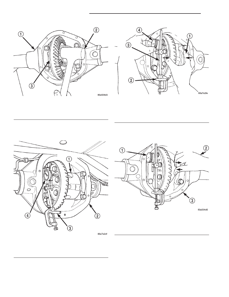
Fig. 86 Seat Ring Gear Side Differential Dummy

Side Bearing

1 – AXLE HOUSING
2 – MALLET
3 – DIFFERENTIAL CASE

Fig. 87 Differential Side play Measurement

1 – DIFFERENTIAL CASE
2 – AXLE HOUSING
3 – SPECIAL TOOL C-3288–B
4 – SPECIAL TOOL C-3339

Fig. 88 Hold Differential Case and Zero Dial

Indicator

1 – FORCE DIFFERENTIAL CASE TO PINION GEAR SIDE
2 – SPECIAL TOOL C-3288–B
3 – SPECIAL TOOL C-3339
4 – ZERO DIAL INDICATOR FACE

Fig. 89 Hold Differential Case and Read Dial

Indicator

1 – READ DIAL INDICATOR
2 – FORCE DIFFERENTIAL CASE TO RING GEAR SIDE
3 – AXLE HOUSING

3 - 54

TUBE, 181, AND 186 FBI AXLE

XJ

ADJUSTMENTS (Continued)

(17) Install the pinion gear in axle housing. Install

the pinion yoke and establish the correct pinion
rotating torque.

(18) Install differential case and dummy bearings

D-348 in axle housing (without shims), install bear-
ing caps and tighten bolts snug.

(19) Seat ring gear side dummy bearing (Fig. 86).
(20) Position the dial indicator plunger on a flat

surface between the ring gear bolt heads. (Fig. 87).

(21) Push and hold differential case toward pinion

gear (Fig. 90).

(22) Zero dial indicator face to pointer (Fig. 90).

(23) Push and hold differential case to ring gear

side of the axle housing (Fig. 91).

(24) Record dial indicator reading (Fig. 91).
(25) Subtract 0.002 in. (0.05 mm) from the dial

indicator reading to compensate for backlash between
ring and pinion gears. This total is the thickness
shim required to achieve proper backlash.

(26) Subtract the backlash shim thickness from

the total preload shim thickness. The remainder is
the shim thickness required on the pinion side of the
axle housing.

(27) Rotate dial indicator out of the way on guide

stud.

(28) Remove differential case and dummy bearings

from axle housing.

(29) Install the selected side bearing shims onto

the differential case hubs.

(30) Install side bearings and cups on differential

case.

(31) Install spreader W-129-B, utilizing some items

from Adapter Set 6987, on axle housing and spread
axle opening enough to receive differential case.

(32) Install differential case into the axle housing.
(33) Remove spreader from axle housing.
(34) Rotate the differential case several times to

seat the side bearings.

(35) Position the indicator plunger against a ring

gear tooth (Fig. 92).

(36) Push and hold ring gear upward while not

allowing the pinion gear to rotate.

(37) Zero dial indicator face to pointer.
(38) Push and hold ring gear downward while not

allowing the pinion gear to rotate. Dial indicator
reading should be between 0.12 mm (0.005 in.) and
0.20 mm (0.008 in.). If backlash is not within specifi-
cations transfer the necessary amount of shim thick-
ness from one side of the axle housing to the other
(Fig. 93).

(39) Verify differential case and ring gear runout

by measuring ring to pinion gear backlash at eight
locations around the ring gear. Readings should not
vary more than 0.05 mm (0.002 in.). If readings vary
more than specified, the ring gear or the differential
case is defective.

After the proper backlash is achieved, perform

Gear Contact Pattern Analysis procedure.

Fig. 90 Hold Differential Case and Zero Dial

Indicator

1 – ZERO DIAL INDICATOR FACE
2 – FORCE DIFFERENTIAL CASE TO PINION GEAR SIDE
3 – PINION GEAR
4 – AXLE HOUSING
5 – DIFFERENTIAL CASE

Fig. 91 Hold Differential Case and Read Dial

Indicator

1 – READ DIAL INDICATOR
2 – FORCE DIFFERENTIAL CASE TO RING GEAR SIDE
3 – PINION GEAR
4 – AXLE HOUSING
5 – DIFFERENTIAL CASE

XJ

TUBE, 181, AND 186 FBI AXLE

3 - 55

ADJUSTMENTS (Continued)

186 FBI DIFFERENTIAL BEARING PRELOAD
AND GEAR BACKLASH

INTRODUCTION

Differential side bearing preload and gear backlash

is achieved by selective shims positioned behind the
differential side bearing cones. The proper shim
thickness can be determined using slip-fit dummy
bearings D-348 in place of the differential side bear-
ings and a dial indicator C-3339. Before proceeding
with the differential bearing preload and gear back-
lash measurements, measure the pinion gear depth
and prepare the pinion for installation. Establishing

proper pinion gear depth is essential to establishing
gear backlash and tooth contact patterns. After the
overall shim thickness to take up differential side
play is measured, the pinion is installed, and the
gear backlash shim thickness is measured. The over-
all shim thickness is the total of the dial indicator
reading and the preload specification added together.
The gear backlash measurement determines the
thickness of the shim used on the ring gear side of
the differential case. Subtract the gear backlash shim
thickness from the total overall shim thickness and
select that amount for the pinion gear side of the dif-
ferential (Fig. 94). Differential shim measurements
are performed with axle spreader W-129-B removed.

SHIM SELECTION

NOTE: It is difficult to salvage the differential side
bearings during the removal procedure. Install
replacement bearings if necessary.

(1) Remove differential side bearings from differ-

ential case.

(2) Remove factory installed shims from differen-

tial case.

(3) Install ring gear on differential case and

tighten bolts to specification.

(4) Install dummy side bearings D-348 on differen-

tial case.

(5) Install differential case in axle housing.

Fig. 92 Ring Gear Backlash Measurement

1 – DIAL INDICATOR

Fig. 93 Backlash Shim Adjustment

Fig. 94 Axle Adjustment Shim Locations

1 – PINION GEAR DEPTH SHIM/OIL BAFFLE
2 – DIFFERENTIAL BEARING SHIM

3 - 56

TUBE, 181, AND 186 FBI AXLE

XJ

ADJUSTMENTS (Continued)

(6) Install the marked bearing caps in their correct

positions. Install and snug the bolts (Fig. 95).

(7) Using a dead-blow type mallet, seat the differ-

ential dummy bearings to each side of the axle hous-
ing (Fig. 96) and (Fig. 97).

(8) Thread guide stud C-3288-B into rear cover

bolt hole below ring gear (Fig. 98).

(9) Attach a dial indicator C-3339 to guide stud.

Position the dial indicator plunger on a flat surface
between the ring gear bolt heads (Fig. 98).

(10) Push and hold differential case to pinion gear

side of axle housing (Fig. 99).

(11) Zero dial indicator face to pointer (Fig. 99).

(12) Push and hold differential case to ring gear

side of the axle housing (Fig. 100).

(13) Record dial indicator reading (Fig. 100).
(14) Add 0.008 in. (0.2 mm) to the zero end play

total. This new total represents the thickness of

Fig. 95 Tighten Bolts Holding Bearing Caps

1 – BEARING CAP
2 – AXLE HOUSING
3 – DIFFERENTIAL CASE

Fig. 96 Seat Pinion Gear Side Differential Dummy

Side Bearing

1 – MALLET
2 – AXLE HOUSING
3 – DIFFERENTIAL CASE

Fig. 97 Seat Ring Gear Side Differential Dummy

Side Bearing

1 – AXLE HOUSING
2 – MALLET
3 – DIFFERENTIAL CASE

Fig. 98 Differential Side play Measurement

1 – DIFFERENTIAL CASE
2 – AXLE HOUSING
3 – SPECIAL TOOL C-3288–B
4 – SPECIAL TOOL C-3339

XJ

TUBE, 181, AND 186 FBI AXLE

3 - 57

ADJUSTMENTS (Continued)


Content   ..  24  25  26  27   ..