Jeep Wrangler TJ. Manual - part 465


  Index      Jeep     Jeep Wrangler TJ - service repair manual 2005 year


Search            


Content   ..  463  464  465  466   ..


Jeep Wrangler TJ. Manual - part 465


The o-rings and spacer will remain in quick-con-
nect fitting connector body.
(9) Plastic Retainer Ring Type Fitting: This

type of fitting can be identified by the use of a full-
round plastic retainer ring (Fig. 33) usually black in
color.

(a) To release fuel system component from quick-

connect fitting, firmly push fitting towards compo-
nent being serviced while firmly pushing plastic
retainer ring into fitting (Fig. 33). With plastic ring

depressed, pull fitting from component. The plas-
tic retainer ring must be pressed squarely
into fitting body. If this retainer is cocked
during removal, it may be difficult to discon-
nect fitting. Use an open-end wrench on
shoulder of plastic retainer ring to aid in dis-
connection.

(b) After disconnection, plastic retainer ring will

remain with quick-connect fitting connector body.

(c) Inspect fitting connector body, plastic retainer

ring and fuel system component for damage.
Replace as necessary.
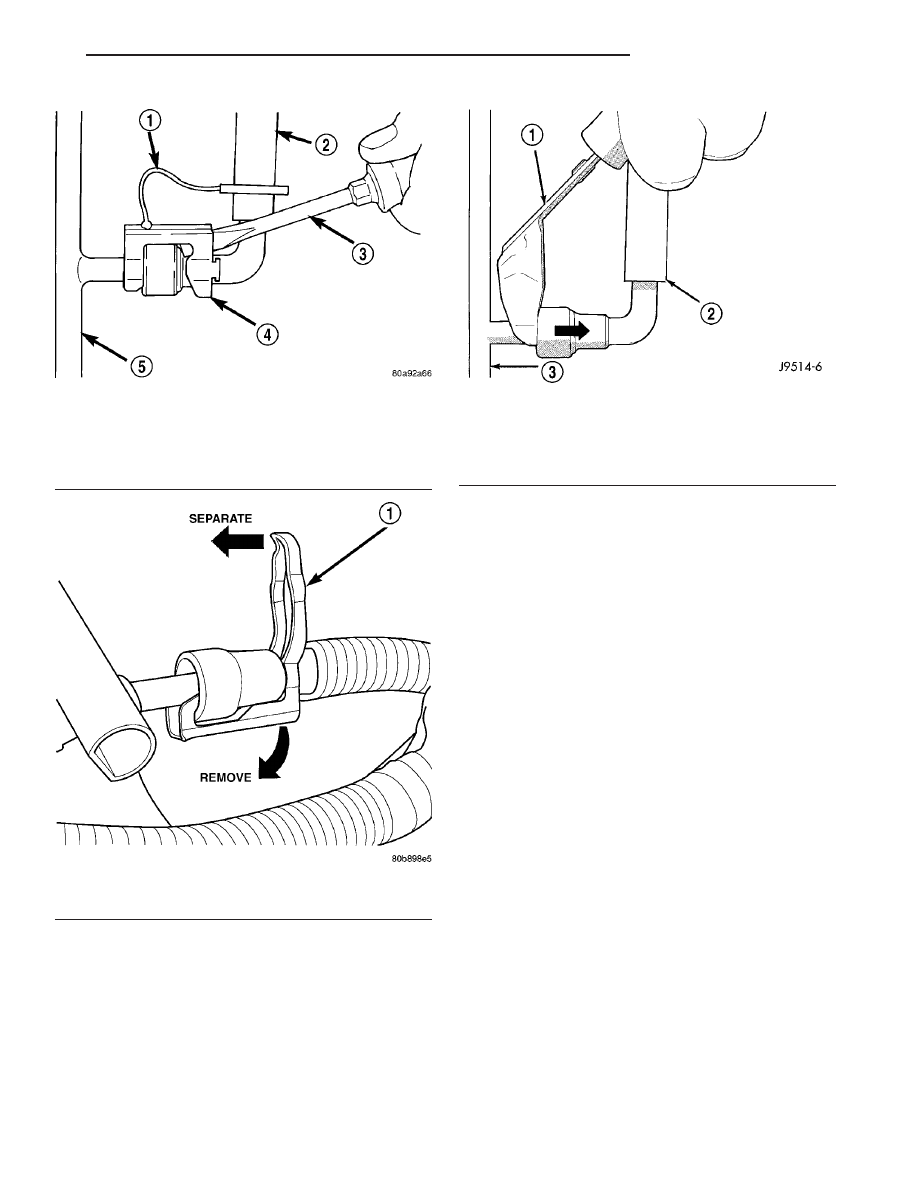
(10) Latch Clips: Depending on vehicle model and

engine, 2 different types of safety latch clips are used
(Fig. 34) or (Fig. 35). Type-1 is tethered to fuel line
and type-2 is not. A special tool will be necessary to
disconnect fuel line after latch clip is removed. The
latch clip may be used on certain fuel line/fuel rail
connection, or to join fuel lines together.

(a) Type 1: Pry up on latch clip with a screw-

driver (Fig. 34).

(b) Type 2: Separate and unlatch 2 small arms

on end of clip (Fig. 35) and swing away from fuel
line.

(c) Slide latch clip toward fuel rail while lifting

with screwdriver.

(d) Insert special fuel line removal tool (Snap-On

number FIH 9055-1 or equivalent) into fuel line
(Fig. 36). Use tool to release locking fingers in end
of line.

(e) With special tool still inserted, pull fuel line

from fuel rail.

(f) After

disconnection,

locking

fingers

will

remain within quick-connect fitting at end of fuel
line.

Fig. 34 LATCH CLIP-TYPE 1

1 - TETHER STRAP
2 - FUEL LINE
3 - SCREWDRIVER
4 - LATCH CLIP
5 - FUEL RAIL

Fig. 35 LATCH CLIP-TYPE 2

1 - LATCH CLIP

Fig. 36 FUEL LINE DISCONNECTION USING

SPECIAL TOOL

1 - SPECIAL FUEL LINE TOOL
2 - FUEL LINE
3 - FUEL RAIL

TJ

FUEL DELIVERY

14 - 19

QUICK CONNECT FITTING (Continued)

(11) Disconnect quick-connect fitting from fuel sys-

tem component being serviced.

CONNECTING

(1) Inspect quick-connect fitting body and fuel sys-

tem component for damage. Replace as necessary.

(2) Prior to connecting quick-connect fitting to

component being serviced, check condition of fitting
and component. Clean parts with a lint-free cloth.
Lubricate with clean engine oil.

(3) Insert quick-connect fitting into fuel tube or

fuel system component until built-on stop on fuel
tube or component rests against back of fitting.

(4) Continue pushing until a click is felt.
(5) Single-tab type fitting: Push new tab down

until it locks into place in quick-connect fitting.

(6) Verify a locked condition by firmly pulling on

fuel tube and fitting (15-30 lbs.).

(7) Latch Clip Equipped: Install latch clip (snaps

into position). If safety latch clip will not fit, this
indicates fuel line is not properly installed to
fuel rail (or other fuel line). Recheck fuel line
connection.

(8) Connect negative cable to battery.
(9) Start engine and check for leaks.

14 - 20

FUEL DELIVERY

TJ

QUICK CONNECT FITTING (Continued)

FUEL INJECTION

TABLE OF CONTENTS

page

page

FUEL INJECTION

DESCRIPTION

. . . . . . . . . . . . . . . . . . . . . . . . . 22

SPECIFICATIONS

TORQUE - FUEL INJECTION

. . . . . . . . . . . . . 22

ACCELERATOR PEDAL

REMOVAL

. . . . . . . . . . . . . . . . . . . . . . . . . . . . . 23

INSTALLATION

. . . . . . . . . . . . . . . . . . . . . . . . . 23

CRANKSHAFT POSITION SENSOR

DESCRIPTION

. . . . . . . . . . . . . . . . . . . . . . . . . 23

OPERATION

. . . . . . . . . . . . . . . . . . . . . . . . . . . 23

REMOVAL

. . . . . . . . . . . . . . . . . . . . . . . . . . . . . 24

INSTALLATION

. . . . . . . . . . . . . . . . . . . . . . . . . 25

FUEL INJECTOR

DESCRIPTION

. . . . . . . . . . . . . . . . . . . . . . . . . 27

OPERATION

OPERATION - PCM OUTPUT

. . . . . . . . . . . . 27

OPERATION - FUEL INJECTOR

. . . . . . . . . . 27

REMOVAL

. . . . . . . . . . . . . . . . . . . . . . . . . . . . . 27

INSTALLATION

. . . . . . . . . . . . . . . . . . . . . . . . . 28

FUEL PUMP RELAY

DESCRIPTION

. . . . . . . . . . . . . . . . . . . . . . . . . 28

OPERATION

. . . . . . . . . . . . . . . . . . . . . . . . . . . 28

REMOVAL

. . . . . . . . . . . . . . . . . . . . . . . . . . . . . 28

INSTALLATION

. . . . . . . . . . . . . . . . . . . . . . . . . 28

IDLE AIR CONTROL MOTOR

DESCRIPTION

. . . . . . . . . . . . . . . . . . . . . . . . . 28

OPERATION

. . . . . . . . . . . . . . . . . . . . . . . . . . . 28

REMOVAL

. . . . . . . . . . . . . . . . . . . . . . . . . . . . . 29

INSTALLATION

. . . . . . . . . . . . . . . . . . . . . . . . . 30

INTAKE AIR TEMPERATURE SENSOR

DESCRIPTION

. . . . . . . . . . . . . . . . . . . . . . . . . 30

OPERATION

. . . . . . . . . . . . . . . . . . . . . . . . . . . 30

REMOVAL

. . . . . . . . . . . . . . . . . . . . . . . . . . . . . 30

INSTALLATION

. . . . . . . . . . . . . . . . . . . . . . . . . 31

MAP SENSOR

DESCRIPTION

. . . . . . . . . . . . . . . . . . . . . . . . . 31

OPERATION

. . . . . . . . . . . . . . . . . . . . . . . . . . . 31

REMOVAL

. . . . . . . . . . . . . . . . . . . . . . . . . . . . . 32

INSTALLATION

. . . . . . . . . . . . . . . . . . . . . . . . . 33

O2 HEATER RELAY

DESCRIPTION

. . . . . . . . . . . . . . . . . . . . . . . . . 34

OPERATION

. . . . . . . . . . . . . . . . . . . . . . . . . . . 34

REMOVAL

. . . . . . . . . . . . . . . . . . . . . . . . . . . . . 34

INSTALLATION

. . . . . . . . . . . . . . . . . . . . . . . . . 34

O2 SENSOR

DESCRIPTION

. . . . . . . . . . . . . . . . . . . . . . . . . 34

OPERATION

. . . . . . . . . . . . . . . . . . . . . . . . . . . 34

REMOVAL

. . . . . . . . . . . . . . . . . . . . . . . . . . . . . 35

INSTALLATION

. . . . . . . . . . . . . . . . . . . . . . . . . 36

THROTTLE BODY

DESCRIPTION

. . . . . . . . . . . . . . . . . . . . . . . . . 36

OPERATION

. . . . . . . . . . . . . . . . . . . . . . . . . . . 36

REMOVAL

. . . . . . . . . . . . . . . . . . . . . . . . . . . . . 37

INSTALLATION

. . . . . . . . . . . . . . . . . . . . . . . . . 37

THROTTLE CONTROL CABLE

REMOVAL

. . . . . . . . . . . . . . . . . . . . . . . . . . . . . 38

INSTALLATION

. . . . . . . . . . . . . . . . . . . . . . . . . 40

THROTTLE POSITION SENSOR

DESCRIPTION

. . . . . . . . . . . . . . . . . . . . . . . . . 40

OPERATION

. . . . . . . . . . . . . . . . . . . . . . . . . . . 40

REMOVAL

. . . . . . . . . . . . . . . . . . . . . . . . . . . . . 40

INSTALLATION

. . . . . . . . . . . . . . . . . . . . . . . . . 41

TJ

FUEL INJECTION

14 - 21

FUEL INJECTION

DESCRIPTION

The Powertrain Control Module (PCM) operates the

fuel injection system. Refer to Powertrain Control Mod-
ule in Electronic Control Modules for information.

SPECIFICATIONS

TORQUE - FUEL INJECTION

DESCRIPTION

N-m

Ft. Lbs.

In. Lbs.

Accelerator Pedal Bracket

Mounting Nuts

8.5

-

75

Engine Coolant

Temperature Sensor -

2.4L/4.0L

11

-

96

IAC Motor-To-Throttle

Body Bolts - 2.4L/4.0L

7

-

60

Intake Manifold Air Temp.

Sensor - 4.0L

28

20

-

MAP Sensor Mounting

Screws - 2.4L/4.0L

3

-

25

Oxygen Sensor -

2.4L/4.0L

30

22

-

PCM Mounting Screws

4

-

35

Throttle Body Mounting

Bolts - 2.4L/4.0L

11

-

100

Throttle Position Sensor

Mounting Screws -

2.4L/4.0L

7

-

60

Vehicle Speed Sensor

Mounting Bolt

2.2

-

20

14 - 22

FUEL INJECTION

TJ


Content   ..  463  464  465  466   ..