Jeep Wrangler TJ. Manual - part 460


  Index      Jeep     Jeep Wrangler TJ - service repair manual 2005 year


Search            


Content   ..  458  459  460  461   ..


Jeep Wrangler TJ. Manual - part 460


REAR TOW HOOK

REMOVAL

(1) Remove the fasteners that attach the rear tow

hook to the frame (Fig. 14).

(2) Separate the tow hook from the frame.

INSTALLATION

(1) Position the tow hook on the frame.
(2) Install the bolts and tighten to 77 N·m (57 ft.

lbs.).

TRANSMISSION SKID PLATE

REMOVAL

(1) Raise

and

support

the

vehicle.

(Refer

to

LUBRICATION

&

MAINTENANCE/HOISTING

-

STANDARD PROCEDURE)

(2) Support the skid plate.
(3) Remove the bolts and remove the skid plate.

(Fig. 15)

INSTALLATION

(1) Position the skid plate in place and support.
(2) Install the bolts and tighten the plate to frame

bolts to 45 N·m (33 ft. lbs.).

(3) Tighten the plate to transfer case skid plate

bolts to 35 N·m (26 ft. lbs.).

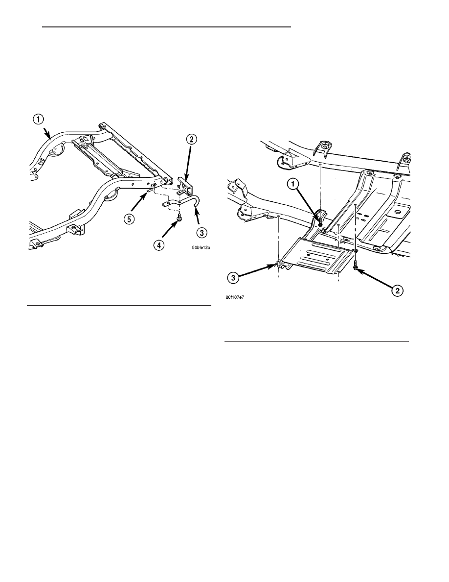
Fig. 14 REAR TOW HOOK

1 - FRAME
2 - REAR BUMPER
3 - TOW HOOK
4 - BOLT
5 - NUT

Fig. 15 TRANSMISSION SKID PLATE

1 - FRONT BOLTS (2)
2 - REAR BOLTS (2)
3 - SKID PLATE

TJ

FRAME & BUMPERS

13 - 11

FUEL SYSTEM

TABLE OF CONTENTS

page

page

FUEL DELIVERY

. . . . . . . . . . . . . . . . . . . . . . . . . . 1

FUEL INJECTION

. . . . . . . . . . . . . . . . . . . . . . . . 21

FUEL DELIVERY

TABLE OF CONTENTS

page

page

FUEL DELIVERY

DESCRIPTION

. . . . . . . . . . . . . . . . . . . . . . . . . . 1

OPERATION

. . . . . . . . . . . . . . . . . . . . . . . . . . . . 1

STANDARD PROCEDURE - FUEL SYSTEM

PRESSURE RELEASE

. . . . . . . . . . . . . . . . . . . 2

SPECIFICATIONS

FUEL SYSTEM PRESSURE

. . . . . . . . . . . . . . 2

TORQUE - FUEL DELIVERY

. . . . . . . . . . . . . . 2

SPECIAL TOOLS

FUEL SYSTEM

. . . . . . . . . . . . . . . . . . . . . . . . 3

FUEL PRESSURE REGULATOR

DESCRIPTION

. . . . . . . . . . . . . . . . . . . . . . . . . . 3

FUEL LEVEL SENDING UNIT / SENSOR

DESCRIPTION

. . . . . . . . . . . . . . . . . . . . . . . . . . 3

FUEL LINES

DESCRIPTION

. . . . . . . . . . . . . . . . . . . . . . . . . . 3

FUEL PUMP

DESCRIPTION

. . . . . . . . . . . . . . . . . . . . . . . . . . 3

FUEL PUMP MODULE

DESCRIPTION

. . . . . . . . . . . . . . . . . . . . . . . . . . 4

REMOVAL

. . . . . . . . . . . . . . . . . . . . . . . . . . . . . 5

INSTALLATION

. . . . . . . . . . . . . . . . . . . . . . . . . . 5

FUEL RAIL/FUEL DAMPER - 2.4L

DESCRIPTION - 2.4L

. . . . . . . . . . . . . . . . . . . . . 6

OPERATION - 2.4L

. . . . . . . . . . . . . . . . . . . . . . . 6

REMOVAL - 2.4L

. . . . . . . . . . . . . . . . . . . . . . . . . 6

INSTALLATION - 2.4L

. . . . . . . . . . . . . . . . . . . . . 7

FUEL RAIL - 4.0L ENGINE

DESCRIPTION - 4.0L

. . . . . . . . . . . . . . . . . . . . . 8

OPERATION - 4.0L

. . . . . . . . . . . . . . . . . . . . . . . 8

REMOVAL - 4.0L

. . . . . . . . . . . . . . . . . . . . . . . . . 8

INSTALLATION - 4.0L

. . . . . . . . . . . . . . . . . . . . . 8

FUEL TANK

DESCRIPTION

. . . . . . . . . . . . . . . . . . . . . . . . . . 9

OPERATION

. . . . . . . . . . . . . . . . . . . . . . . . . . . . 9

REMOVAL

. . . . . . . . . . . . . . . . . . . . . . . . . . . . . 10

INSTALLATION

. . . . . . . . . . . . . . . . . . . . . . . . . 12

INLET FILTER

REMOVAL

. . . . . . . . . . . . . . . . . . . . . . . . . . . . . 15

INSTALLATION

. . . . . . . . . . . . . . . . . . . . . . . . . 15

QUICK CONNECT FITTING

DESCRIPTION

. . . . . . . . . . . . . . . . . . . . . . . . . 16

STANDARD PROCEDURE - QUICK-CONNECT

FITTINGS

. . . . . . . . . . . . . . . . . . . . . . . . . . . 16

FUEL DELIVERY

DESCRIPTION

The fuel delivery system consists of:
• the fuel pump module containing the electric

fuel pump, fuel filter/fuel pressure regulator, fuel
gauge sending unit (fuel level sensor) and a separate
fuel filter located at bottom of pump module

• fuel tubes/lines/hoses

• quick-connect fittings

• fuel injector rail

• fuel injectors

• fuel tank

• fuel tank filler/vent tube assembly

• fuel tank filler tube cap

• check valve(s)

• accelerator pedal

• throttle cable

OPERATION

Fuel is returned through the fuel pump module

and back into the fuel tank through the fuel filter/
fuel pressure regulator. A separate fuel return line
from the engine to the tank is not used.

The fuel tank assembly consists of: the fuel tank,

fuel pump module assembly, fuel pump module lock-
nut/gasket, and fuel tank check valve (refer to Emis-

TJ

FUEL SYSTEM

14 - 1

sion Control System for fuel tank check valve
information).

A fuel filler/vent tube assembly using a pressure/

vacuum fuel filler cap is used. The fuel filler tube
contains a flap door located below the fuel fill cap.

Also to be considered part of the fuel system is the

evaporation control system. This is designed to
reduce the emission of fuel vapors into the atmo-
sphere. The description and function of the Evapora-
tive Control System is located in Emission Control
Systems.

Both fuel filters (at bottom of fuel pump module

and within fuel pressure regulator) are designed for
extended service. They do not require normal sched-
uled maintenance. Filters should only be replaced if
a diagnostic procedure indicates to do so.

STANDARD PROCEDURE - FUEL SYSTEM
PRESSURE RELEASE

Use following procedure if the fuel injector

rail is, or is not equipped with a fuel pressure
test port.

(1) Remove fuel fill cap.
(2) Remove fuel pump relay from Power Distribu-

tion Center (PDC). For location of relay, refer to label
on underside of PDC cover.

(3) Start and run engine until it stalls.
(4) Attempt restarting engine until it will no

longer run.

(5) Turn ignition key to OFF position.

CAUTION: Steps 1, 2, 3 and 4 must be performed to
relieve high pressure fuel from within fuel rail. Do

not attempt to use following steps to relieve this
pressure as excessive fuel will be forced into a cyl-
inder chamber.

(6) Unplug connector from any fuel injector.
(7) Attach one end of a jumper wire with alligator

clips (18 gauge or smaller) to either injector terminal.

(8) Connect other end of jumper wire to positive

side of battery.

(9) Connect one end of a second jumper wire to

remaining injector terminal.

CAUTION: Powering an injector for more than a few
seconds will permanently damage the injector.

(10) Momentarily touch other end of jumper wire

to negative terminal of battery for no more than a
few seconds.

(11) Place a rag or towel below fuel line quick-con-

nect fitting at fuel rail.

(12) Disconnect quick-connect fitting at fuel rail.

Refer to Quick-Connect Fittings.

(13) Return fuel pump relay to PDC.
(14) One or more Diagnostic Trouble Codes (DTC’s)

may have been stored in PCM memory due to fuel
pump relay removal. The DRB

t scan tool must be

used to erase a DTC.

SPECIFICATIONS

FUEL SYSTEM PRESSURE

58 psi +/- 2 psi

TORQUE - FUEL DELIVERY

DESCRIPTION

N-m

Ft. Lbs.

In. Lbs.

Accelerator Pedal Bracket

Mounting Nuts

8.5

-

75

Fuel Hose Clamps

3

-

25

Fuel Rail Mounting Bolts -

2.4L

28

-

250

Fuel Rail Mounting Bolts

or Nuts - 4.0L

11

-

100

Fuel Tank Mounting Strap

Bolts

Refer to service manual

text.

-

-

Fuel Tank Skidplate Bolts

16

-

141

14 - 2

FUEL DELIVERY

TJ

FUEL DELIVERY (Continued)


Content   ..  458  459  460  461   ..