Jeep Wrangler TJ. Manual - part 417


  Index      Jeep     Jeep Wrangler TJ - service repair manual 2005 year


Search            


Content   ..  415  416  417  418   ..


Jeep Wrangler TJ. Manual - part 417


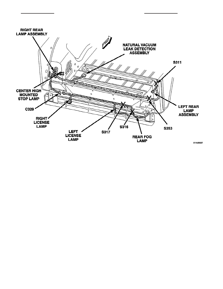
Fig. 42 -REAR LAMPS (RHD)

TJ

8W-91 CONNECTOR/GROUND/SPLICE LOCATION

8W - 91 - 47

CONNECTOR/GROUND/SPLICE LOCATION (Continued)

8W-97 POWER DISTRIBUTION

TABLE OF CONTENTS

page

page

POWER DISTRIBUTION

DESCRIPTION

. . . . . . . . . . . . . . . . . . . . . . . . . . 1

OPERATION

. . . . . . . . . . . . . . . . . . . . . . . . . . . . 1

SPECIAL TOOLS

POWER DISTRIBUTION SYSTEMS

. . . . . . . . . 2

CIGAR LIGHTER OUTLET

DESCRIPTION

. . . . . . . . . . . . . . . . . . . . . . . . . . 2

OPERATION

. . . . . . . . . . . . . . . . . . . . . . . . . . . . 2

DIAGNOSIS AND TESTING - CIGAR LIGHTER

OUTLET

. . . . . . . . . . . . . . . . . . . . . . . . . . . . . 2

FUSE BLOCK

DESCRIPTION

. . . . . . . . . . . . . . . . . . . . . . . . . . 3

OPERATION

. . . . . . . . . . . . . . . . . . . . . . . . . . . . 4

REMOVAL

. . . . . . . . . . . . . . . . . . . . . . . . . . . . . 4

INSTALLATION

. . . . . . . . . . . . . . . . . . . . . . . . . . 4

IOD FUSE

DESCRIPTION

. . . . . . . . . . . . . . . . . . . . . . . . . . 5

OPERATION

. . . . . . . . . . . . . . . . . . . . . . . . . . . . 5

REMOVAL

. . . . . . . . . . . . . . . . . . . . . . . . . . . . . 5

INSTALLATION

. . . . . . . . . . . . . . . . . . . . . . . . . . 5

MICRO-RELAY

DESCRIPTION

. . . . . . . . . . . . . . . . . . . . . . . . . . 6

OPERATION

. . . . . . . . . . . . . . . . . . . . . . . . . . . . 6

DIAGNOSIS AND TESTING - MICRO-RELAY

. . . 6

REMOVAL

. . . . . . . . . . . . . . . . . . . . . . . . . . . . . 6

INSTALLATION

. . . . . . . . . . . . . . . . . . . . . . . . . . 6

POWER DISTRIBUTION CENTER

DESCRIPTION

. . . . . . . . . . . . . . . . . . . . . . . . . . 7

OPERATION

. . . . . . . . . . . . . . . . . . . . . . . . . . . . 7

REMOVAL

. . . . . . . . . . . . . . . . . . . . . . . . . . . . . 7

DISASSEMBLY

POWER DISTRIBUTION CENTER

DISASSEMBLY . . . . . . . . . . . . . . . . . . . . . . . . 8

ASSEMBLY

POWER DISTRIBUTION CENTER

ASSEMBLY . . . . . . . . . . . . . . . . . . . . . . . . . . 10

INSTALLATION

. . . . . . . . . . . . . . . . . . . . . . . . . 11

POWER DISTRIBUTION CENTER SUPPORT

BRACKET
REMOVAL

. . . . . . . . . . . . . . . . . . . . . . . . . . . . . 12

INSTALLATION

. . . . . . . . . . . . . . . . . . . . . . . . . 12

POWER OUTLET

DESCRIPTION

. . . . . . . . . . . . . . . . . . . . . . . . . 12

OPERATION

. . . . . . . . . . . . . . . . . . . . . . . . . . . 12

DIAGNOSIS AND TESTING - POWER OUTLET

. 13

REMOVAL

. . . . . . . . . . . . . . . . . . . . . . . . . . . . . 13

INSTALLATION

. . . . . . . . . . . . . . . . . . . . . . . . . 13

RELAY

DESCRIPTION

. . . . . . . . . . . . . . . . . . . . . . . . . 14

OPERATION

. . . . . . . . . . . . . . . . . . . . . . . . . . . 14

DIAGNOSIS AND TESTING - RELAY

. . . . . . . . . 14

REMOVAL

. . . . . . . . . . . . . . . . . . . . . . . . . . . . . 15

INSTALLATION

. . . . . . . . . . . . . . . . . . . . . . . . . 15

POWER DISTRIBUTION

DESCRIPTION

This

group

covers

the

various

standard

and

optional power distribution components used on this
model. The power distribution system for this vehicle
consists of the following components:

• Power Distribution Center (PDC)

• Fuseblock

• Cigar Lighter Outlet

• Power Outlet
The power distribution system also incorporates

various types of circuit control and protection fea-
tures, including:

• Blade-type fuses

• Cartridge fuses

• Relays
Following are general descriptions of the major

components in the power distribution system. See the

owner’s manual in the vehicle glove box for more
information on the features and use of all of the
power distribution system components. Refer to the
index in this service manual for the location of com-
plete circuit diagrams for the various power distribu-
tion system components.

OPERATION

The power distribution system for this vehicle is

designed to provide safe, reliable, and centralized dis-
tribution points for the electrical current required to
operate all of the many standard and optional facto-
ry-installed

electrical

and

electronic

powertrain,

chassis, safety, security, comfort and convenience sys-
tems. At the same time, the power distribution sys-
tem was designed to provide ready access to these
electrical distribution points for the vehicle techni-
cian to use when conducting diagnosis and repair of
faulty circuits. The power distribution system can
also prove useful for the sourcing of additional elec-

TJ

8W-97 POWER DISTRIBUTION

8W - 97 - 1

trical circuits that may be required to provide the
electrical current needed to operate many accessories
that the vehicle owner may choose to have installed
in the aftermarket.

SPECIAL TOOLS

POWER DISTRIBUTION SYSTEMS

CIGAR LIGHTER OUTLET

DESCRIPTION

An instrument panel cigar lighter outlet is stan-

dard factory-installed equipment on some models.
Models equipped with the optional smoker’s package
will include a cigar lighter knob and heating ele-
ment. Models without the smoker’s package are
equipped with a snap fit plastic cap and the outlet is
treated as an extra accessory power outlet. The out-
let is installed in the instrument panel accessory
switch bezel, which is located near the bottom of the
instrument panel center bezel area, below the heater
and air conditioner controls.

The cigar lighter outlet is serviced only as a part of

the accessory switch bezel unit. If the base is faulty
or damaged, the accessory switch bezel unit must be
replaced. The cigar lighter knob and heating element
unit is available for service. This component cannot
be repaired and, if faulty or damaged, it must be
replaced.

OPERATION

The cigar lighter base or receptacle shell is con-

nected to ground, and an insulated contact in the
bottom of the shell is connected to battery current.
The cigar lighter receives battery voltage from a fuse
(f13) in the Power Distribution Center (PDC) through
the ignition switch, only when in the Accessory or On
position and through a fuse (f19) in the fuseblock.

8

The cigar lighter knob and heating element are

encased within a spring-loaded housing, which also
features a sliding protective heat shield. When the
knob and heating element are inserted in the recep-
tacle shell, the heating element resistor coil is
grounded through its housing to the receptacle shell.
If the cigar lighter knob is pushed inward, the heat
shield slides up toward the knob exposing the heat-
ing element, and the heating element extends from
the housing toward the insulated contact in the bot-
tom of the receptacle shell.

Two small spring-clip retainers are located on

either side of the insulated contact inside the bottom
of the receptacle shell. These clips engage and hold
the heating element of the cigar lighter against the
insulated contact long enough for the resistor coil to
heat up. When the heating element is engaged with
the contact, battery current can flow through the
resistor coil to ground, causing the resistor coil to
heat.

When the resistor coil becomes sufficiently heated,

excess heat radiates from the heating element caus-
ing the spring-clips to expand. Once the spring-clips
expand far enough to release the heating element,
the spring-loaded housing forces the knob and heat-
ing element to pop back outward to their relaxed
position. When the cigar lighter knob and element
are pulled out of the receptacle shell, the protective
heat shield slides downward on the housing so that
the heating element is recessed and shielded around
its circumference for safety.

DIAGNOSIS AND TESTING - CIGAR LIGHTER
OUTLET

For complete circuit diagrams, refer to Wiring

Diagrams.

WARNING: REFER TO THE RESTRAINTS SECTION
OF THE SERVICE MANUAL BEFORE ATTEMPTING
ANY STEERING WHEEL, STEERING COLUMN, OR
INSTRUMENT PANEL COMPONENT DIAGNOSIS OR
SERVICE. FAILURE TO TAKE THE PROPER PRE-
CAUTIONS COULD RESULT IN ACCIDENTAL AIR-
BAG DEPLOYMENT AND POSSIBLE PERSONAL
INJURY.

(1) Remove the cigar lighter knob and element

from the cigar lighter receptacle shell. Check for con-
tinuity between the inside circumference of the cigar
lighter receptacle shell and a good ground. there
should be continuity. If OK, go to Step 2. If not OK,
go to Step 3.

(2) Turn the ignition switch to the On position.

Check for battery voltage at the insulated contact
located at the back of the cigar lighter receptacle

Terminal Pick Kit 6680

8W - 97 - 2

8W-97 POWER DISTRIBUTION

TJ

POWER DISTRIBUTION (Continued)


Content   ..  415  416  417  418   ..