Jeep Wrangler TJ. Manual - part 328


  Index      Jeep     Jeep Wrangler TJ - service repair manual 2005 year


Search            


Content   ..  326  327  328  329   ..


Jeep Wrangler TJ. Manual - part 328


secures the turning loop to the height adjuster on the
upper sport bar (Fig. 42).

(2) Remove the screw that secures the shoulder

belt turning loop to the height adjuster.

(3) Remove the front seat belt turning loop and the

support/guide washer from the height adjuster.

(4) Unsnap and remove the trim cover from the

front seat belt turning loop height adjuster to access
the screws that secure the adjuster to the upper
sport bar.

(5) Remove the two screws that secure the height

adjuster to the upper sport bar.

(6) Remove the front seat belt turning loop height

adjuster from the upper sport bar.

INSTALLATION

WARNING:

TO

AVOID

PERSONAL

INJURY

OR

DEATH, DURING AND FOLLOWING ANY SEAT BELT
OR CHILD RESTRAINT ANCHOR SERVICE, CARE-
FULLY INSPECT ALL SEAT

BELTS,

BUCKLES,

MOUNTING HARDWARE, RETRACTORS, TETHER
STRAPS, AND ANCHORS FOR PROPER INSTALLA-
TION, OPERATION, OR DAMAGE. REPLACE ANY
BELT

THAT

IS

CUT,

FRAYED,

OR

TORN.

STRAIGHTEN

ANY

BELT

THAT

IS

TWISTED.

TIGHTEN ANY LOOSE FASTENERS. REPLACE ANY
BELT THAT HAS A DAMAGED OR INOPERATIVE
BUCKLE OR RETRACTOR. REPLACE ANY BELT
THAT HAS A BENT OR DAMAGED LATCH PLATE
OR

ANCHOR

PLATE.

REPLACE

ANY

CHILD

RESTRAINT ANCHOR OR THE UNIT TO WHICH THE
ANCHOR IS INTEGRAL THAT HAS BEEN BENT OR
DAMAGED. NEVER ATTEMPT TO REPAIR A SEAT
BELT

OR

CHILD

RESTRAINT

COMPONENT.

ALWAYS REPLACE DAMAGED OR FAULTY SEAT
BELT AND CHILD RESTRAINT COMPONENTS WITH
THE CORRECT, NEW AND UNUSED REPLACEMENT
PARTS LISTED IN THE DAIMLERCHRYSLER MOPAR
PARTS CATALOG.

(1) Position the front seat belt turning loop height

adjuster onto the upper sport bar (Fig. 42). Be cer-
tain that the word “Up” stamped on the adjuster is
properly oriented.

(2) Install and tighten the two screws that secure

the seat belt turning loop height adjuster to the
upper sport bar. Tighten the screws to 43 N·m (32 ft.
lbs.).

(3) Align the trim cover over the front seat belt

turning loop height adjuster and, using hand pres-
sure, press firmly and evenly on the cover until it
snaps into place over the adjuster on the upper sport
bar.

(4) Position the support/guide washer and the

front seat belt turning loop onto the height adjuster.

(5) Install and tighten the screw that secures the

front seat belt turning loop to the height adjuster.
Tighten the screw to 43 N·m (32 ft. lbs.).

(6) Fold and snap the trim cover for the seat belt

turning loop back into place over the screw that
secures the turning loop to the height adjuster.

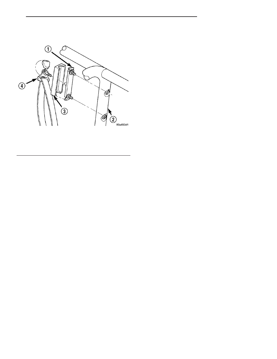
Fig. 42 Front Turning Loop Height Adjuster

1 - ADJUSTER
2 - SPORT BAR
3 - TRIM COVER
4 - TURNING LOOP

TJ

RESTRAINTS

8O - 37

SEAT BELT TURNING LOOP ADJUSTER (Continued)

SPEED CONTROL

TABLE OF CONTENTS

page

page

SPEED CONTROL

DESCRIPTION

. . . . . . . . . . . . . . . . . . . . . . . . . . 1

OPERATION

. . . . . . . . . . . . . . . . . . . . . . . . . . . . 1

DIAGNOSIS AND TESTING - ROAD TEST

. . . . . 2

SPECIFICATIONS

TORQUE - SPEED CONTROL

. . . . . . . . . . . . . 2

CABLE

DESCRIPTION

. . . . . . . . . . . . . . . . . . . . . . . . . . 3

OPERATION

. . . . . . . . . . . . . . . . . . . . . . . . . . . . 3

REMOVAL

. . . . . . . . . . . . . . . . . . . . . . . . . . . . . 3

INSTALLATION

. . . . . . . . . . . . . . . . . . . . . . . . . . 3

SERVO

DESCRIPTION

. . . . . . . . . . . . . . . . . . . . . . . . . . 4

OPERATION

. . . . . . . . . . . . . . . . . . . . . . . . . . . . 4

REMOVAL

. . . . . . . . . . . . . . . . . . . . . . . . . . . . . 4

INSTALLATION

. . . . . . . . . . . . . . . . . . . . . . . . . . 5

SWITCH

DESCRIPTION

. . . . . . . . . . . . . . . . . . . . . . . . . . 5

OPERATION

. . . . . . . . . . . . . . . . . . . . . . . . . . . . 5

REMOVAL

. . . . . . . . . . . . . . . . . . . . . . . . . . . . . 6

INSTALLATION

. . . . . . . . . . . . . . . . . . . . . . . . . . 6

VACUUM RESERVOIR

DESCRIPTION

. . . . . . . . . . . . . . . . . . . . . . . . . . 7

OPERATION

. . . . . . . . . . . . . . . . . . . . . . . . . . . . 7

DIAGNOSIS AND TESTING - VACUUM

RESERVOIR

. . . . . . . . . . . . . . . . . . . . . . . . . . 7

REMOVAL

. . . . . . . . . . . . . . . . . . . . . . . . . . . . . 7

INSTALLATION

. . . . . . . . . . . . . . . . . . . . . . . . . . 7

SPEED CONTROL

DESCRIPTION

The speed control system is electronically con-

trolled and vacuum operated. Electronic control of
the speed control system is integrated into the Pow-
ertrain Control Module (PCM). The controls consist
of

two

steering

wheel

mounted

switches.

The

switches are labeled: ON/OFF, RES/ACCEL, SET,
COAST, and CANCEL.

The system is designed to operate at speeds above

30 mph (50 km/h).

WARNING: THE USE OF SPEED CONTROL IS NOT
RECOMMENDED WHEN DRIVING CONDITIONS DO
NOT PERMIT MAINTAINING A CONSTANT SPEED,
SUCH AS IN HEAVY TRAFFIC OR ON ROADS THAT
ARE WINDING, ICY, SNOW COVERED, OR SLIP-
PERY.

OPERATION

When speed control is selected by depressing the

ON switch, the PCM allows a set speed to be stored
in PCM RAM for speed control. To store a set speed,
depress the SET switch while the vehicle is moving
at a speed between 35 and 85 mph. In order for the
speed control to engage, the brakes cannot be
applied, nor can the gear selector be indicating the
transmission is in Park or Neutral.

The speed control can be disengaged manually by:
• Stepping on the brake pedal

• Depressing the OFF switch

• Depressing the CANCEL switch.

• Depressing the clutch pedal (if equipped).

NOTE: Depressing the OFF switch or turning off the
ignition switch will erase the set speed stored in
the PCM.

For added safety, the speed control system is pro-

grammed to disengage for any of the following condi-
tions:

• An indication of Park or Neutral

• A rapid increase rpm (indicates that the clutch

has been disengaged)

• Excessive engine rpm (indicates that the trans-

mission may be in a low gear)

• The speed signal increases at a rate of 10 mph

per second (indicates that the coefficient of friction
between the road surface and tires is extremely low)

• The speed signal decreases at a rate of 10 mph

per second (indicates that the vehicle may have
decelerated at an extremely high rate)

Once the speed control has been disengaged,

depressing the RES/ACCEL switch (when speed is
greater than 30 mph) restores the vehicle to the tar-
get speed that was stored in the PCM.

While the speed control is engaged, the driver can

increase the vehicle speed by depressing the RES/AC-
CEL switch. The new target speed is stored in the
PCM when the RES/ACCEL is released. The PCM
also has a

9tap-up9 feature in which vehicle speed

increases at a rate of approximately 2 mph for each
momentary switch activation of the RES/ACCEL
switch.

TJ

SPEED CONTROL

8P - 1

A “tap down” feature is used to decelerate without

disengaging the speed control system. To decelerate
from an existing recorded target speed, momentarily
depress the COAST switch. For each switch activa-
tion, speed will be lowered approximately 1 mph.

OVERSHOOT/UNDERSHOOT

If the vehicle operator repeatedly presses and

releases the SET button with their foot off of the
accelerator (referred to as a “lift foot set”), the vehicle
may accelerate and exceed the desired set speed by
up to 5 mph (8 km/h). It may also decelerate to less
than the desired set speed, before finally achieving
the desired set speed.

The Speed Control System has an adaptive strat-

egy that compensates for vehicle-to-vehicle variations
in speed control cable lengths. When the speed con-
trol is set with the vehicle operators foot off of the
accelerator pedal, the speed control thinks there is
excessive speed control cable slack and adapts
accordingly. If the “lift foot sets” are continually used,
a speed control overshoot/undershoot condition will
develop.

To “unlearn” the overshoot/undershoot condition,

the vehicle operator has to press and release the set
button while maintaining the desired set speed using
the accelerator pedal (not decelerating or accelerat-
ing), and then turning the cruise control switch to
the OFF position (or press the CANCEL button if
equipped) after waiting 10 seconds. This procedure
must be performed approximately 10–15 times to
completely unlearn the overshoot/undershoot condi-
tion.

DIAGNOSIS AND TESTING - ROAD TEST

Perform a vehicle road test to verify reports of

speed control system malfunction. The road test

should include attention to the speedometer. Speed-
ometer operation should be smooth and without flut-
ter at all speeds.

Flutter in the speedometer indicates a problem

which might cause surging in the speed control sys-
tem. The cause of any speedometer problems should
be corrected before proceeding. Refer to Group 8J,
Instrument Cluster for speedometer diagnosis.

If a road test verifies a system problem and the

speedometer operates properly, check for:

• A Diagnostic Trouble Code (DTC). If a DTC

exists, conduct tests per the Powertrain Diagnostic
Procedures service manual.

• A misadjusted brake (stop) lamp switch. This

could also cause an intermittent problem.

• Loose, damaged or corroded electrical connec-

tions at the servo. Corrosion should be removed from
electrical terminals and a light coating of Mopar
MultiPurpose Grease, or equivalent, applied.

• Leaking vacuum reservoir.

• Loose or leaking vacuum hoses or connections.

• Defective one-way vacuum check valve.

• Secure attachment of both ends of the speed con-

trol servo cable.

• Smooth operation of throttle linkage and throttle

body air valve.

• Failed speed control servo. Do the servo vacuum

test.

CAUTION: When test probing for voltage or conti-
nuity at electrical connectors, care must be taken
not to damage connector, terminals or seals. If
these components are damaged, intermittent or
complete system failure may occur.

SPECIFICATIONS

TORQUE - SPEED CONTROL

DESCRIPTION

N-m

Ft. Lbs.

In. Lbs.

Servo Mounting Bracket-

to-Servo Nuts

8.5

-

75

Speed Control Switch

Mounting Screws

1.5

-

14

Vacuum Reservoir

Mounting Bolt (screw)

1.2

-

10

8P - 2

SPEED CONTROL

TJ

SPEED CONTROL (Continued)


Content   ..  326  327  328  329   ..