Jeep Wrangler TJ. Manual - part 282


  Index      Jeep     Jeep Wrangler TJ - service repair manual 2005 year


Search            


Content   ..  280  281  282  283   ..


Jeep Wrangler TJ. Manual - part 282


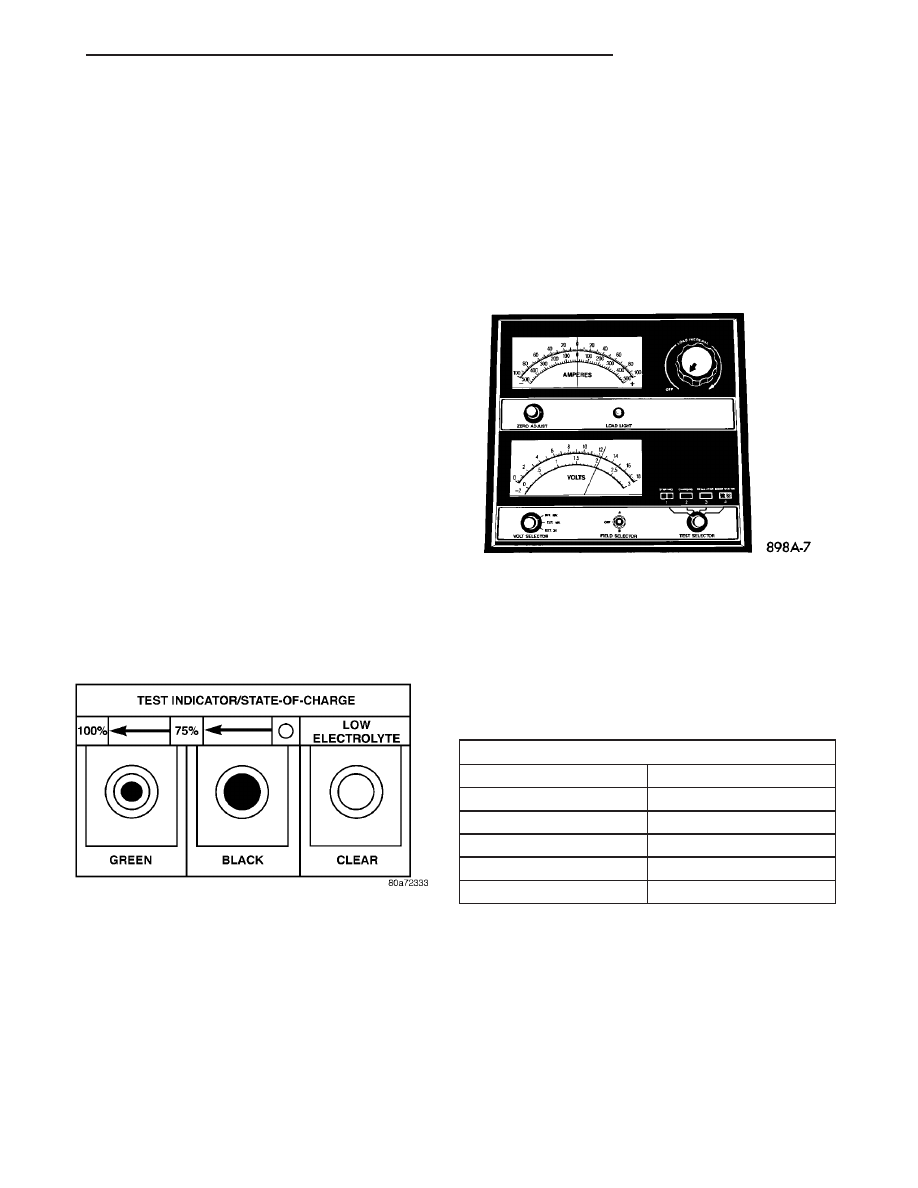
To read the built-in indicator, look into the sight

glass and note the color of the indication (Fig. 7). The
battery

condition

that

each

color

indicates

is

described in the following list:

• Green - Indicates 75% to 100% battery state-of-

charge. The battery is adequately charged for further
testing or return to service. If the starter will not
crank for a minimum of fifteen seconds with a fully-
charged battery, the battery must be load tested.
Refer to Standard Procedures for the proper battery
load test procedures.

• Black or Dark - Indicates 0% to 75% battery

state-of-charge. The battery is inadequately charged
and must be charged until a green indication is visi-
ble in the sight glass (12.4 volts or more), before the
battery is tested further or returned to service. Refer
to Standard Procedures for the proper battery charg-
ing procedures. Also refer to Diagnosis and Testing
for more information on the possible causes of the
discharged battery condition.

• Clear or Bright - Indicates a low battery elec-

trolyte level. The electrolyte level in the battery is
below the built-in indicator. A maintenance-free bat-
tery with non-removable cell caps must be replaced if
the electrolyte level is low. Water must be added to a
low-maintenance battery with removable cell caps
before it is charged. Refer to Standard Procedures for
the proper battery filling procedures. A low electro-
lyte level may be caused by an overcharging condi-
tion. Refer to Charging System for the proper
charging system diagnosis and testing procedures.

STANDARD PROCEDURE - OPEN-CIRCUIT
VOLTAGE TEST

A battery open-circuit voltage (no load) test will

show the approximate state-of-charge of a battery.
This test can be used in place of the hydrometer test
when a hydrometer is not available, or for mainte-
nance-free batteries with non-removable cell caps.

Before proceeding with this test, completely charge

the battery (Refer to 8 - ELECTRICAL/BATTERY
SYSTEM/BATTERY - STANDARD PROCEDURE).

(1) Before measuring the open-circuit voltage, the

surface charge must be removed from the battery.
Turn on the headlamps for fifteen seconds, then
allow up to five minutes for the battery voltage to
stabilize.

(2) Disconnect and isolate both battery cables, neg-

ative cable first.

(3) Using a voltmeter connected to the battery

posts (see the instructions provided by the manufac-
turer of the voltmeter), measure the open-circuit volt-
age (Fig. 8).

See the Open-Circuit Voltage Table. This voltage

reading will indicate the battery state-of-charge, but
will not reveal its cranking capacity. If a battery has
an open-circuit voltage reading of 12.4 volts or
greater, it may be load tested to reveal its cranking
capacity (Refer to 8 - ELECTRICAL/BATTERY SYS-
TEM/BATTERY - STANDARD PROCEDURE).

OPEN CIRCUIT VOLTAGE TABLE

Open Circuit Voltage

Charge Percentage

11.7 volts or less

0%

12.0 volts

25%

12.2 volts

50%

12.4 volts

75%

12.6 volts or more

100%

STANDARD PROCEDURE - IGNITION-OFF
DRAW TEST

The term Ignition-Off Draw (IOD) identifies a nor-

mal condition where power is being drained from the
battery with the ignition switch in the Off position. A
normal vehicle electrical system will draw from five
to thirty-five milliamperes (0.005 to 0.035 ampere)
with the ignition switch in the Off position, and all
non-ignition controlled circuits in proper working
order. Up to thirty-five milliamperes are needed to
enable the memory functions for the Powertrain Con-

Fig. 7 Built-In Indicator Sight Glass Chart

Fig. 8 Testing Open-Circuit Voltage - Typical

TJ

BATTERY SYSTEM

8F - 11

BATTERY (Continued)

trol Module (PCM), digital clock, electronically tuned
radio, and other modules which may vary with the
vehicle equipment.

A vehicle that has not been operated for approxi-

mately twenty days, may discharge the battery to an
inadequate level. When a vehicle will not be used for
twenty days or more (stored), remove the IOD fuse
from the Power Distribution Center (PDC). This will
reduce battery discharging.

Excessive IOD can be caused by:
• Electrical items left on.

• Faulty or improperly adjusted switches.

• Faulty or shorted electronic modules and compo-

nents.

• An internally shorted generator.

• Intermittent shorts in the wiring.
If the IOD is over thirty-five milliamperes, the

problem must be found and corrected before replac-
ing a battery. In most cases, the battery can be
charged and returned to service after the excessive
IOD condition has been corrected.

(1) Verify that all electrical accessories are off.

Turn off all lamps, remove the ignition key, and close
all doors. If the vehicle is equipped with an illumi-
nated entry system or an electronically tuned radio,
allow the electronic timer function of these systems
to automatically shut off (time out). This may take
up to three minutes.

(2) Determine that the underhood lamp is operat-

ing properly, then disconnect the lamp wire harness
connector or remove the lamp bulb.

(3) Disconnect the battery negative cable.
(4) Set an electronic digital multi-meter to its

highest amperage scale. Connect the multi-meter
between the disconnected battery negative cable ter-
minal clamp and the battery negative terminal post.
Make sure that the doors remain closed so that the
illuminated entry system is not activated. The multi-
meter amperage reading may remain high for up to
three minutes, or may not give any reading at all
while set in the highest amperage scale, depending
upon the electrical equipment in the vehicle. The
multi-meter leads must be securely clamped to the
battery negative cable terminal clamp and the bat-
tery negative terminal post. If continuity between the
battery negative terminal post and the negative cable
terminal clamp is lost during any part of the IOD
test, the electronic timer function will be activated
and all of the tests will have to be repeated.

(5) After about three minutes, the high-amperage

IOD reading on the multi-meter should become very
low or nonexistent, depending upon the electrical
equipment in the vehicle. If the amperage reading
remains high, remove and replace each fuse or circuit
breaker in the Power Distribution Center (PDC) and
then in the Junction Block (JB), one at a time until

the amperage reading becomes very low, or nonexist-
ent. Refer to the appropriate wiring information in
this service manual for complete PDC and JB fuse,
circuit breaker, and circuit identification. This will
isolate each circuit and identify the circuit that is the
source of the high-amperage IOD. If the amperage
reading remains high after removing and replacing
each fuse and circuit breaker, disconnect the wire
harness from the generator. If the amperage reading
now becomes very low or nonexistent, refer to Charg-
ing System for the proper charging system diagnosis
and testing procedures. After the high-amperage IOD
has been corrected, switch the multi-meter to pro-
gressively lower amperage scales and, if necessary,
repeat the fuse and circuit breaker remove-and-re-
place process to identify and correct all sources of
excessive IOD. It is now safe to select the lowest mil-
liampere scale of the multi-meter to check the low-
amperage IOD.

CAUTION: Do not open any doors, or turn on any
electrical accessories with the lowest milliampere
scale selected, or the multi-meter may be damaged.

(6) Observe the multi-meter reading. The low-am-

perage IOD should not exceed thirty-five milliam-
peres (0.035 ampere). If the current draw exceeds
thirty-five milliamperes, isolate each circuit using the
fuse and circuit breaker remove-and-replace process
in Step 5. The multi-meter reading will drop to
within the acceptable limit when the source of the
excessive current draw is disconnected. Repair this
circuit as required; whether a wiring short, incorrect
switch adjustment, or a component failure is at fault.

STANDARD PROCEDURE - USING MICRO 420
BATTERY TESTER

Always use the Micro 420 Instruction Manual that

was supplied with the tester as a reference. If the
Instruction Manual is not available the following pro-
cedure can be used:

WARNING: ALWAYS

WEAR APPROPRIATE

EYE

PROTECTION AND USE EXTREME CAUTION WHEN
WORKING WITH BATTERIES.

BATTERY TESTING

(1) If testing the battery OUT-OF-VEHICLE, clean

the battery terminals with a wire brush before test-
ing. If the battery is equipped with side post termi-
nals, install and tighten the supplied lead terminal
stud adapters. Do not use steel bolts. Failure to prop-
erly install the stud adapters, or using stud adapters
that are dirty or worn-out may result in false test
readings.

8F - 12

BATTERY SYSTEM

TJ

BATTERY (Continued)

(2) If testing the battery IN-THE-VEHICLE, make

certain all of the vehicle accessory loads are OFF,
including the ignition. The preferred test position
is at the battery terminal
. If the battery is not
accessible, you may test using both the positive and
negative jumper posts. Select TESTING AT JUMPER
POST when connecting to that location.

(3) Connect the tester (Fig. 9) to the battery or

jumper posts, the red clamp to positive (+) and the
black clamp to negative (–).

NOTE: Multiple batteries connected in parallel must
have the ground cable disconnected to perform a
battery test. Failure to disconnect may result in
false battery test readings.

(4) Using the ARROW key select in or out of vehi-

cle testing and press ENTER to make a selection.

(5) If not selected, choose the Cold Cranking Amp

(CCA) battery rating. Or select the appropriate bat-
tery rating for your area (see menu). The tester will
then run its self programmed test of the battery and
display the results. Refer to the test result table
noted below.

CAUTION: If REPLACE BATTERY is the result of the
test, this may mean a poor connection between the
vehicle’s cables and battery exists. After discon-
necting the vehicle’s battery cables from the bat-
tery, retest the battery using the OUT-OF-VEHICLE
test before replacing.

(6) While viewing the battery test result, press the

CODE button and the tester will prompt you for the

last 4 digits of the VIN. Use the UP/DOWN arrow
buttons to scroll to the correct character; then press
ENTER to select and move to the next digit. Then
press the ENTER button to view the SERVICE
CODE. Pressing the CODE button a second time will
return you to the test results.

BATTERY TEST RESULTS

GOOD BATTERY

Return to service

GOOD - RECHARGE

Fully charge battery and

return to service

CHARGE & RETEST

Fully charge battery and

retest battery

REPLACE BATTERY

Replace the battery and

retest complete system

BAD-CELL REPLACE

Replace the battery and

retest complete system

NOTE: The SERVICE CODE is required on every
warranty claim submitted for battery replacement.

REMOVAL

(1) Turn the ignition switch to the Off position. Be

certain that all electrical accessories are turned off.

(2) Loosen the battery negative cable terminal

clamp pinch-bolt hex nut.

(3) Disconnect the battery negative cable terminal

clamp from the battery negative terminal post. If
necessary, use a battery terminal puller to remove
the terminal clamp from the battery post (Fig. 10).

(4) Loosen the battery positive cable terminal

clamp pinch-bolt hex nut.

(5) Disconnect the battery positive cable terminal

clamp from the battery positive terminal post. If nec-
essary, use a battery terminal puller to remove the
terminal clamp from the battery post.

Fig. 9 Micro 420 Battery Tester

Fig. 10 Remove Battery Cable Terminal Clamp -

Typical

1 - BATTERY
2 - BATTERY TERMINAL PULLER

TJ

BATTERY SYSTEM

8F - 13

BATTERY (Continued)

(6) Remove the battery holddowns from the bat-

tery. Refer to Battery Holddown for the proper bat-
tery holddown removal procedures.

WARNING: WEAR A SUITABLE PAIR OF RUBBER
GLOVES (NOT THE HOUSEHOLD TYPE) WHEN
REMOVING

A

BATTERY

BY

HAND.

SAFETY

GLASSES SHOULD ALSO BE WORN. IF THE BAT-
TERY IS CRACKED OR LEAKING, THE ELECTRO-
LYTE CAN BURN THE SKIN AND EYES.

(7) Remove the battery and the battery thermal

guard from the battery tray as a unit.

(8) Remove the battery thermal guard from the

battery case. Refer to Thermal Guard for the proper
battery thermal guard removal procedures.

INSTALLATION

(1) Clean and inspect all of the battery system

components. Refer to Battery System Cleaning for
the proper cleaning procedures, and refer to Battery
System Inspection for the proper inspection proce-
dures.

(2) Reinstall the battery thermal guard onto the

battery case. Refer to Thermal Guard for the proper
battery thermal guard installation procedures.

(3) Position the battery and the battery thermal

guard onto the battery tray as a unit. Ensure that
the battery positive and negative terminal posts are
correctly positioned. The battery cable terminal
clamps must reach the correct battery terminal post
without stretching the cables (Fig. 11).

(4) Reinstall the battery holddowns onto the bat-

tery. Refer to Battery Holddown for the proper instal-
lation procedure.

CAUTION: Be certain that the battery cable terminal
clamps are connected to the correct battery termi-
nal posts. Reversed battery polarity may damage
electrical components of the vehicle.

(5) Clean the battery cable terminal clamps and

the battery terminal posts. Refer to Battery System
Cleaning for cleaning procedure.

(6) Reconnect the battery positive cable terminal

clamp to the battery positive terminal post. Tighten
the terminal clamp pinch-bolt hex nut to 8.4 N·m (75
in. lbs.).

(7) Reconnect the battery negative cable terminal

clamp to the battery negative terminal post. Tighten
the terminal clamp pinch-bolt hex nut to 8.4 N·m (75
in. lbs.).

(8) Apply a thin coating of petroleum jelly or chas-

sis grease to the exposed surfaces of the battery cable
terminal clamps and the battery terminal posts.

BATTERY HOLDDOWN

DESCRIPTION

The battery hold down hardware (Fig. 12) includes

two J-bolts, a hold down bracket and two hex nuts
with coned washers. The battery hold down bracket
consists of a stamped steel bracket that is then plas-
tic-coated for corrosion protection.

Fig. 11 Battery Cables - Typical

1 - RADIATOR CROSSMEMBER
2 - WHEELHOUSE INNER PANEL
3 - NEGATIVE CABLE
4 - POSITIVE CABLE
5 - BATTERY

Fig. 12 Battery Hold Downs

1 - J-BOLT (2)
2 - NUT (2)
3 - BRACKET
4 - BATTERY

8F - 14

BATTERY SYSTEM

TJ

BATTERY (Continued)


Content   ..  280  281  282  283   ..