Jeep Wrangler TJ. Manual - part 267


  Index      Jeep     Jeep Wrangler TJ - service repair manual 2005 year


Search            


Content   ..  265  266  267  268   ..


Jeep Wrangler TJ. Manual - part 267


REMOVAL

(1) Drain cooling system below thermostat housing

level.

(2) Disconnect engine coolant temperature sensor.
(3) Disconnect heater supply hose.
(4) Remove housing attaching bolts (Fig. 10).
(5) Remove housing, gasket and thermostat (Fig.

10).

INSTALLATION

INSTALLATION

(1) Install the replacement thermostat so that the

pellet, which is encircled by a coil spring, faces the
engine. All thermostats are marked on the outer
flange to indicate the proper installed position.

(2) Observe the recess groove in the engine cylin-

der head (Fig. 11).

(3) Position thermostat into this groove with arrow

and air bleed hole on outer flange pointing up.

(4)

Install replacement gasket and thermostat

housing.

CAUTION:

Tightening

the

thermostat

housing

unevenly or with the thermostat out of its recess
may result in a cracked housing.

(5) Tighten the housing bolts to 20 N·m (15 ft. lbs.)

torque.

(6) Install hoses to thermostat housing.
(7) Install electrical connector to coolant tempera-

ture sensor.

(8) Be sure that the radiator draincock is tightly

closed. Fill the cooling system (Refer to 7 - COOLING
- STANDARD PROCEDURE).

(9) Start and warm the engine. Check for leaks.

INSTALLATION

(1) Clean all gasket sealing surfaces.
(2) Place a new gasket (dipped in clean water) on

the coolant outlet connector surface. Position thermo-
stat with air bleed at 12 o’clock position in thermo-
stat housing (Fig. 12).

(3) Position the coolant outlet connector and gas-

ket over the thermostat, making sure thermostat is
seated in the thermostat housing.

(4) Position outlet connector to thermostat housing

and install bolts. Tighten bolts to 28 N·m (20 ft. lbs.).

(5) Install radiator hose to coolant outlet housing.
(6) Connect engine coolant temperature sensor.

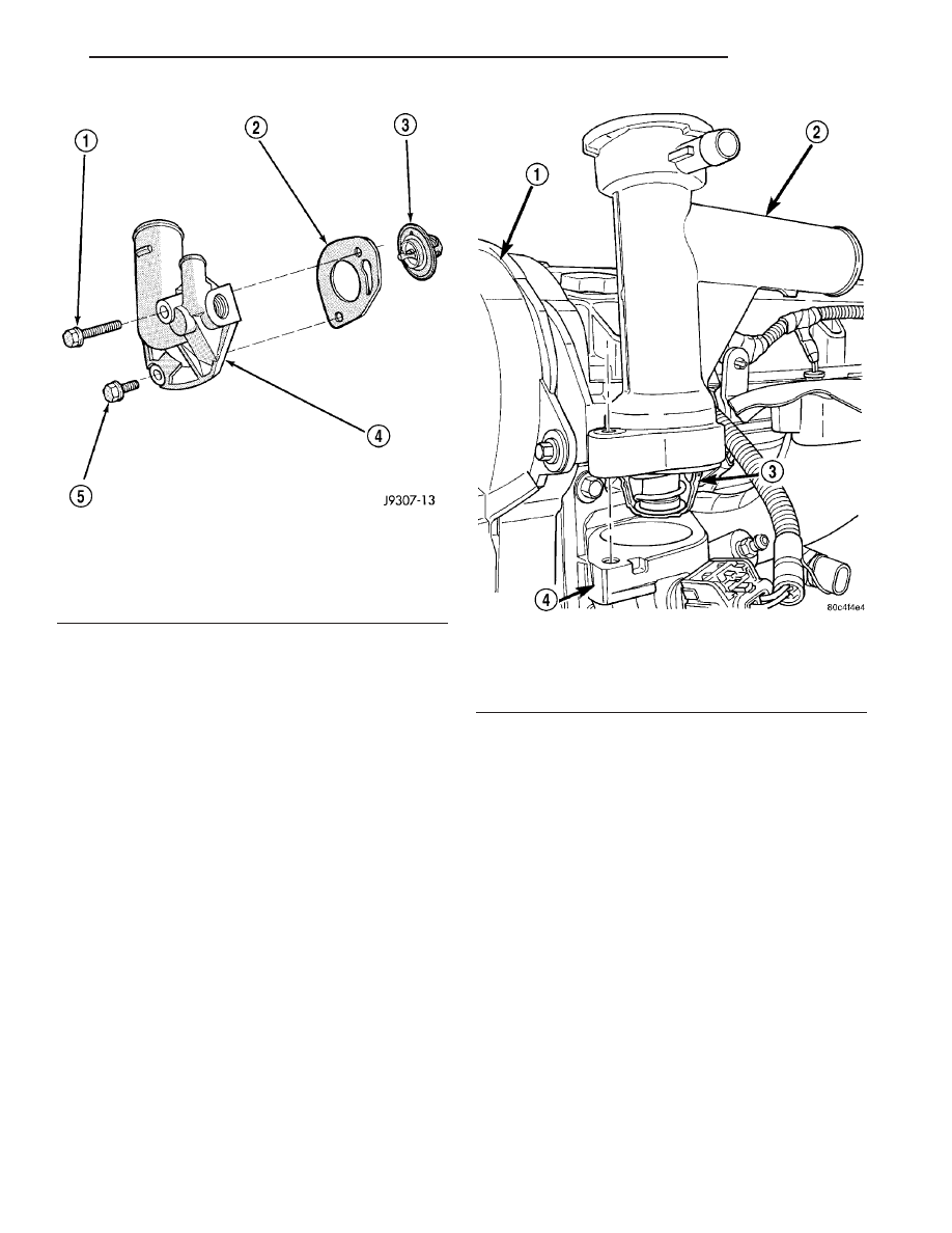
Fig. 9 Thermostat Removal/Installation

1 - LONG BOLT
2 - GASKET
3 - THERMOSTAT
4 - THERMOSTAT HOUSING
5 - SHORT BOLT

Fig. 10 Thermostat and Coolant Outlet Connector

1 - TIMING BELT COVER
2 - OUTLET CONNECTOR
3 - THERMOSTAT
4 - HOUSING

TJ

ENGINE

7 - 29

ENGINE COOLANT THERMOSTAT (Continued)

(7) Fill cooling system (Refer to 7 - COOLING -

STANDARD PROCEDURE).

FAN DRIVE VISCOUS CLUTCH

DESCRIPTION

CAUTION: Engines equipped with serpentine drive
belts have reverse rotating fans and viscous fan
drives. They are marked with the word REVERSE to
designate their usage. Installation of the wrong fan
or viscous fan drive can result in engine overheat-
ing.

The thermal viscous fan drive (Fig. 13) and (Fig.

14) is a silicone-fluid-filled coupling used to connect
the fan blades to the water pump shaft. The coupling
allows the fan to be driven in a normal manner. This
is done at low engine speeds while limiting the top
speed of the fan to a predetermined maximum level
at higher engine speeds.

Fig. 11 Thermostat Recess

1 - GROOVE

Fig. 12 Thermostat Position

1 - LOCATOR NOTCH
2 - AIR BLEED

Fig. 13 Water Pump Mounted Fan Drive - 2.5L

Engine

1 - THERMAL VISCOUS FAN DRIVE
2 - (4) FAN BLADE-TO-VISCOUS DRIVE BOLTS
3 - (4) FAN HUB-TO-PUMP PULLEY STUDS
4 - WATER PUMP
5 - WATER PUMP PULLEY
6 - FAN BLADE
7 - (4) FAN HUB-TO-PUMP PULLEY NUTS

7 - 30

ENGINE

TJ

ENGINE COOLANT THERMOSTAT (Continued)

OPERATION

A thermostatic bimetallic spring coil is located on

the front face of the viscous fan drive unit (a typical
viscous unit is shown in (Fig. 15) (Fig. 16). This
spring coil reacts to the temperature of the radiator
discharge air. It engages the viscous fan drive for
higher fan speed if the air temperature from the
radiator rises above a certain point. Until additional
engine cooling is necessary, the fan will remain at a
reduced rpm regardless of engine speed.

Only when sufficient heat is present, will the vis-

cous fan drive engage. This is when the air flowing
through the radiator core causes a reaction to the
bimetallic coil. It then increases fan speed to provide
the necessary additional engine cooling.

Once the engine has cooled, the radiator discharge

temperature will drop. The bimetallic coil again
reacts and the fan speed is reduced to the previous
disengaged speed.

DIAGNOSIS AND TESTING

VISCOUS FAN DRIVE

NOISE

NOTE: It is normal for fan noise to be louder (roar-
ing) when:

• The under hood temperature is above the

engagement point for the viscous drive coupling. This

may occur when ambient (outside air temperature) is
very high.

• Engine loads and temperatures are high such as

when towing a trailer.

• Cool silicone fluid within the fan drive unit is

being redistributed back to its normal disengaged
(warm) position. This can occur during the first 15
seconds to one minute after engine start-up on a cold
engine.

LEAKS

Viscous fan drive operation is not affected by small

oil stains near the drive bearing. If leakage appears
excessive, replace the fan drive unit.

TESTING

If the fan assembly free-wheels without drag (the

fan blades will revolve more than five turns when

Fig. 14 Water Pump Mounted Fan Drive - 4.0L

Engine

1 - FAN AND FAN DRIVE
2 - WATER PUMP PULLEY

Fig. 15 Viscous Fan Drive - 2.5L Engine

1 - VISCOUS FAN DRIVE
2 - MOUNTING HUB
3 - THERMOSTATIC SPRING

Fig. 16 Viscous Fan Drive - 4.0L Engine

1 - VISCOUS FAN DRIVE
2 - THERMOSTATIC SPRING
3 - MOUNTING NUT TO WATER PUMP HUB

TJ

ENGINE

7 - 31

FAN DRIVE VISCOUS CLUTCH (Continued)

spun by hand), replace the fan drive. This spin test
must be performed when the engine is cool.

For the following test, the cooling system must be

in good condition. It also will ensure against exces-
sively high coolant temperature.

WARNING: BE SURE THAT THERE IS ADEQUATE
FAN BLADE CLEARANCE BEFORE DRILLING.

(1) Drill a 3.18 mm (1/8 in.) diameter hole in the

top center of the fan shroud.

(2) Obtain a dial thermometer with an 8 inch stem

(or equivalent). It should have a range of -18° - 105°C
(-4°- 220° F). Insert thermometer through the hole in
the shroud. Be sure that there is adequate clearance
from the fan blades.

(3) Connect a tachometer and an engine ignition

timing light (timing light is to be used as a strobe
light).

(4) Block the air flow through the radiator. Secure

a sheet of plastic in front of the radiator (or air con-
ditioner condenser). Use tape at the top to secure the
plastic and be sure that the air flow is blocked.

(5) Be sure that the air conditioner (if equipped) is

turned off.

WARNING: USE EXTREME CAUTION WHEN THE
ENGINE IS OPERATING. DO NOT STAND IN A
DIRECT LINE WITH THE FAN. DO NOT PUT YOUR
HANDS NEAR THE PULLEYS, BELTS OR FAN. DO
NOT WEAR LOOSE CLOTHING.

(6) Start the engine and operate at 2400 rpm.

Within ten minutes the air temperature (indicated on
the dial thermometer) should be up to 88° C (190° F).
Fan drive engagement should have started to occur
at between 74° - 85° C (165° - 185° F). Engagement
is distinguishable by a definite increase in fan flow
noise (roaring). The timing light also will indicate an
increase in the speed of the fan.

(7) When the air temperature reaches 88° C (190°

F), remove the plastic sheet. Fan drive disengage-
ment 
should have started to occur at between 57° -
82° C (135° - 180° F). A definite decrease of fan flow
noise (roaring) should be noticed. If not, replace the
defective viscous fan drive unit.

CAUTION: Engines equipped with serpentine drive
belts have reverse rotating fans and viscous fan
drives. They are marked with the word REVERSE to
designate their usage. Installation of the wrong fan
or viscous fan drive can result in engine overheat-
ing.

CAUTION: If the viscous fan drive is replaced
because of mechanical damage, the cooling fan
blades should also be inspected. Inspect for fatigue

cracks, loose blades, or loose rivets that could
have resulted from excessive vibration. Replace fan
blade assembly if any of these conditions are
found. Also inspect water pump bearing and shaft
assembly for any related damage due to a viscous
fan drive malfunction.

REMOVAL

(1) The thermal viscous fan drive/fan blade assem-

bly is attached (threaded) to water pump hub shaft.
Remove fan blade/viscous fan drive assembly from
water pump by turning mounting nut counterclock-
wise as viewed from front. Threads on viscous fan
drive are RIGHT HAND. Using a suitable fan
wrench loosen the fan drive (Fig. 17).

(2) Remove accessory drive belt (Refer to 7 -

COOLING/ACCESSORY

DRIVE/DRIVE

BELTS

-

REMOVAL).

(3) Some models with certain engines may require

the removal of the fan shroud to remove the viscous
fan drive. The fan shroud and fan blade/viscous fan
drive should be removed from the vehicle as one
assembly.

(4) After removing fan blade/viscous fan drive

assembly, do not place thermal viscous fan drive in
horizontal position. If stored horizontally, silicone
fluid in viscous fan drive could drain into its bearing
assembly and contaminate lubricant.

INSTALLATION

(1) Assemble fan blade to viscous fan drive.

Tighten mounting bolts to 27 N·m (20 ft. lbs.) torque.

(2) Thread the fan and fan drive onto the water

pump pulley.

Fig. 17 Fan and Fan Drive - 4.0L Engine

1 - FAN AND FAN DRIVE
2 - WATER PUMP PULLEY

7 - 32

ENGINE

TJ

FAN DRIVE VISCOUS CLUTCH (Continued)


Content   ..  265  266  267  268   ..