Jeep Wrangler TJ. Manual - part 268


  Index      Jeep     Jeep Wrangler TJ - service repair manual 2005 year


Search            


Content   ..  266  267  268  269   ..


Jeep Wrangler TJ. Manual - part 268


CAUTION: When installing a serpentine accessory
drive belt, the belt MUST be routed correctly. If not,
the engine may overheat due to the water pump
rotating in the wrong direction.

(3) Install accessory drive belt (Refer to 7 - COOL-

ING/ACCESSORY DRIVE/DRIVE BELTS - INSTAL-
LATION).

RADIATOR

DESCRIPTION

CAUTION: Plastic tanks, while stronger than brass,
are

subject

to

damage

by

impact,

such

as

wrenches, mishandling, etc.

A heavy duty down-flow aluminum/plastic radiator

is used (Fig. 18). The radiator consists of an alumi-
num core and plastic end tanks, which are fastened
to the core with clinch tabs and sealed with a high
temperature rubber gasket. On automatic transmis-
sion equipped vehicles, the lower tank contains a
concentric-tube transmission oil cooler.

If the plastic tank has been damaged, individual

parts are not available, and the radiator must be
replaced.

OPERATION

As air passes through the radiator core, the heat

within the coolant is dissipated into the ambient air.

DIAGNOSIS AND TESTING - RADIATOR
COOLANT FLOW

The following procedure will determine if coolant is

flowing through the cooling system.

If engine is cold, idle engine until normal operating

temperature is reached. Then feel the upper radiator
hose. If hose is hot, the thermostat is open and water
is circulating through cooling system.

REMOVAL

WARNING:

DO

NOT

REMOVE

THE

CYLINDER

BLOCK DRAIN PLUGS OR LOOSEN THE RADIATOR
DRAINCOCK WITH THE SYSTEM HOT AND PRES-
SURIZED. SERIOUS BURNS FROM THE COOLANT
CAN OCCUR.

Do not waste reusable coolant. If the solution is

clean, drain the coolant into a clean container for
reuse.

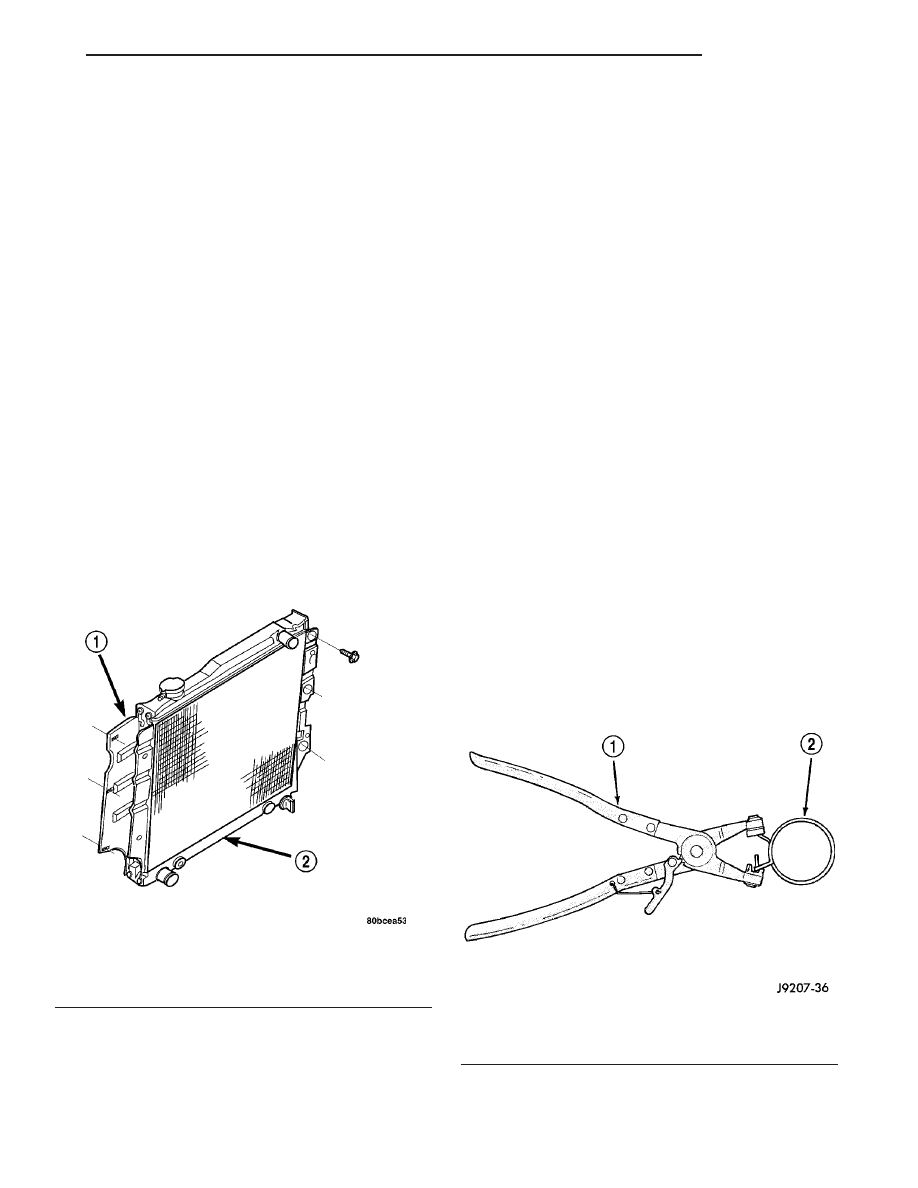
WARNING: CONSTANT TENSION HOSE CLAMPS
ARE USED ON MOST COOLING SYSTEM HOSES.
WHEN REMOVING OR INSTALLING, USE ONLY
TOOLS DESIGNED FOR SERVICING THIS TYPE OF
CLAMP, SUCH AS SPECIAL CLAMP TOOL NUMBER
6094 (Fig. 19). ALWAYS WEAR SAFETY GLASSES
WHEN SERVICING CONSTANT TENSION CLAMPS.

CAUTION: A number or letter is stamped into the
tongue of constant tension clamps (Fig. 20). If
replacement is necessary, use only an original
equipment clamp with matching number or letter.

Fig. 19 Hose Clamp Tool - Typical

1 - HOSE CLAMP TOOL 6094
2 - HOSE CLAMP

Fig. 18 Downflow Radiator - Typical

1 - DOWNFLOW RADIATOR
2 - INTEGRAL TRANSMISSION OIL COOLER (INTERNAL TO
RADIATOR)

TJ

ENGINE

7 - 33

FAN DRIVE VISCOUS CLUTCH (Continued)

CAUTION: When removing the radiator or A/C con-
denser for any reason, note the location of all radi-
ator-to-body and radiator-to-A/C condenser rubber
air seals (Fig. 21). These are used at the top, bot-
tom and sides of the radiator and A/C condenser.
To

prevent

overheating,

these

seals

must

be

installed to their original positions.

(1) Disconnect negative battery cable at battery.

(2) Observe the previous WARNING. Remove the

radiator cap.

(3) Remove the condenser lower seal from the

lower core support (Fig. 22).

(4) Drain cooling system (Refer to 7 - COOLING -

STANDARD PROCEDURE) drain coolant into a
clean container for reuse.

(5) Remove radiator upper and lower hose clamps.

Remove radiator hoses.

(6) Disconnect coolant reserve/overflow tank hose

from radiator.

(7) 2.4L ONLY - Remove the electric cooling fan

(Refer to 7 - COOLING/ENGINE/RADIATOR FAN -
REMOVAL).

(8) 4.0L ONLY - Remove the reservoir tank and

power steering reservoir and position out of the way.

(9) 4.0L ONLY - Remove the four fan shroud

mounting bolts (Fig. 23). Position the fan shroud
back over the fan blades.

(10) If equipped, disconnect and plug automatic

transmission fluid cooler lines.

(11) Remove six radiator mounting bolts. Position

the front axle vent hose (Fig. 23) to the side.

(12) The lower part of radiator is equipped with

two alignment dowel pins (Fig. 24). They are located
on the bottom of radiator tank and fit into rubber
grommets. These rubber grommets are pressed into
the radiator lower crossmember.

(13) Lift radiator straight up and out of vehicle

taking care not to damage radiator fins.

Fig. 20 Clamp Number/Letter Location - Typical

1 - TYPICAL CONSTANT TENSION HOSE CLAMP
2 - CLAMP NUMBER/LETTER LOCATION
3 - TYPICAL HOSE

Fig. 21 Air Seals - Typical

1 - AIR DAM
2 - RADIATOR
3 - AIR DAM
4 - A/C CONDENSER
5 - AIR SEAL

Fig. 22 Condenser Lower Seal

7 - 34

ENGINE

TJ

RADIATOR (Continued)

(14) When removing radiator, note position of the

rubber seals located on the top and bottom of radia-
tor (on certain models only) (Fig. 23). To prevent pos-
sible overheating, these seals must be installed to
their original positions.

CLEANING

Clean radiator fins. With the engine cold, apply

cold water and compressed air to the back (engine
side) of the radiator to flush the radiator and/or A/C
condenser of debris.

INSPECTION

The radiator cooling fins should be checked for

damage or deterioration. Inspect cooling fins to make
sure they are not bent or crushed, these areas result
in reduced heat exchange causing the cooling system
to operate at higher temperatures. Inspect the plastic
end tanks for cracks, damage or leaks.

Inspect the radiator neck for damage or distortion.

Fig. 23 Radiator - Remove/Install

1 - A/C CONDENSER SEALS
2 - FAN SHROUD (4.0L)
3 - FAN SHROUD (2.5L)
4 - TRANSMISSION OIL COOLER LINES RETAINER CLIPS

5 - COOLANT RECOVERY BOTTLE
6 - TRANSMISSION COOLER LINES (IF EQUIPPED)
7 - FRONT AXLE VENT HOSE

Fig. 24 Radiator Alignment Dowels - Typical

1 - RADIATOR
2 - ALIGNMENT DOWEL
3 - RADIATOR LOWER ISOLATOR
4 - RADIATOR LOWER CROSSMEMBER

TJ

ENGINE

7 - 35

RADIATOR (Continued)

INSTALLATION

CAUTION: Before installing the radiator or A/C con-
denser, be sure the radiator-to-body and radiator-to-
A/C

condenser

rubber

air

seals

are

properly

fastened to their original positions. These are used
at the top, bottom and sides of the radiator and A/C
condenser. To prevent overheating, these seals
must be installed to their original positions.

(1) Guide the two radiator alignment dowels into

the rubber grommets located in lower radiator cross-
member. Install and tighten the six mounting bolts
(Fig. 23) to 8 N·m (72 in. lbs.) torque.

(2) Close radiator draincock.
(3) 2.4L ONLY - Install the electric cooling fan

(Refer to 7 - COOLING/ENGINE/RADIATOR FAN -
INSTALLATION).

(4) Position fan shroud and power steering reser-

voir tank (if equipped). Install and tighten four
mounting bolts to 8 N·m (72 in. lbs.) torque.

(5) If equipped, remove plugs and connect auto-

matic transmission fluid cooler lines and constant
tension clamps.

CAUTION: The tangs on the hose clamps must be
positioned straight down.

(6) Connect radiator hoses and install hose clamps.
(7) Position and install the condenser lower seal

(Fig. 22).

(8) Connect battery negative cable.
(9) Fill cooling system with correct coolant (Refer

to 7 - COOLING - STANDARD PROCEDURE).

(10) Connect coolant recovery bottle hose.
(11) Install radiator cap.
(12) Check and adjust automatic transmission

fluid level (if equipped).

(13) Start engine and check for leaks.

WATER PUMP - 2.4L

DESCRIPTION

The water pump has a cast aluminum body and

housing with a stamped steel impeller. The water
pump bolts directly to the block (Fig. 25). The cylin-
der block to water pump seal is provided by a rubber
O-ring. The water pump is driven by the engine tim-
ing belt.

OPERATION

The water pump is the heart of the cooling system.

The coolant is pumped through the engine block, cyl-
inder head, heater core, and radiator.

DIAGNOSIS AND TESTING

WATER PUMP

A quick flow test to determine if the water pump is

working effectively is to check heater system for
proper operation. A defective pump will not provide
an adequate flow of heated coolant through the sys-
tem.

WARNING: DO NOT REMOVE THE COOLING SYS-
TEM PRESSURE CAP WITH THE SYSTEM HOT AND
UNDER PRESSURE BECAUSE SERIOUS BURNS
FROM COOLANT CAN OCCUR.

Another flow test to help determine water pump

operation is as follows:

(1) Remove cooling system pressure cap.
(2) Remove a small amount of coolant from the

system.

(3) Start the engine and warm up until thermostat

opens.

(4) With the thermostat open and coolant level low,

visually inspect for coolant flow. If flow is present,
the water pump is pumping coolant through the sys-
tem.

Fig. 25 Water Pump

1 - CYLINDER BLOCK
2 - WATER PUMP

7 - 36

ENGINE

TJ

RADIATOR (Continued)


Content   ..  266  267  268  269   ..