Jeep Liberty KJ. Manual - part 838


  Index      Jeep     Jeep Liberty KJ - service repair manual 2006 year


Search            


Content   ..  836  837  838  839   ..


Jeep Liberty KJ. Manual - part 838


3.

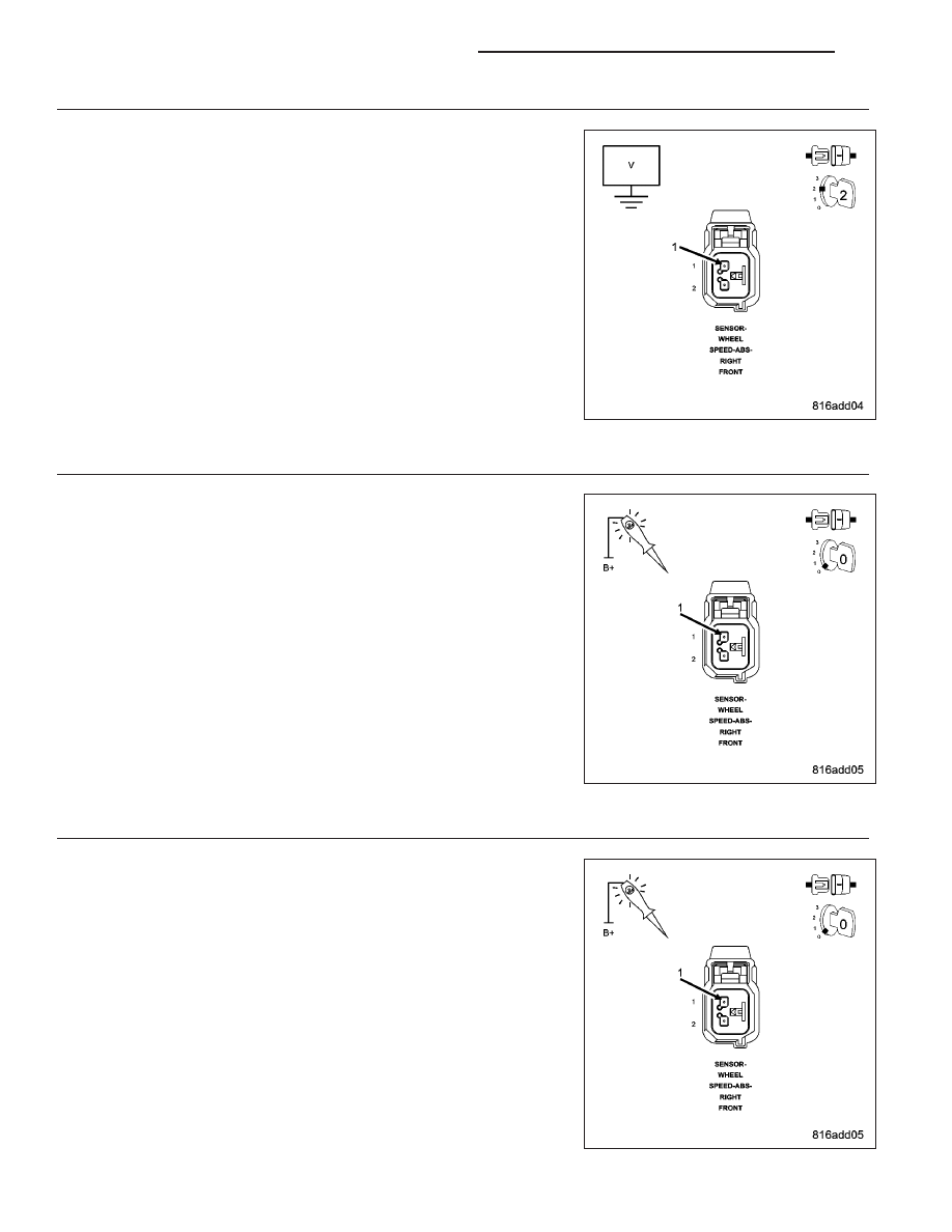
CHECK (B7) RIGHT FRONT WSS 12 VOLT SUPPLY CIRCUIT VOLTAGE

If not done so previously, reconnect the Anti-Lock Brakes Module har-
ness connector.

Disconnect the Right Front WSS harness connector.

Turn the ignition on.

Measure the voltage of the (B7) Right Front WSS 12 Volt Supply circuit.

Is the voltage above 10.0 volts?

Yes

>> Go To 6

No

>> Go To 4

4.

CHECK (B7) RIGHT FRONT WSS 12 VOLT SUPPLY CIRCUIT FOR A SHORT TO GROUND

Turn the ignition off.

Disconnect the Anti-Lock Brakes Module harness connector.

Using a 12-volt test light connected to 12 volts, probe the (B7) Right
Front WSS 12 Volt Supply circuit.

Does the test light illuminate?

Yes

>> Repair the (B7) Right Front WSS 12 Volt Supply circuit for a

short to ground.

Perform ABS VERIFICATION TEST - VER 1. (Refer to 5 -
BRAKES - STANDARD PROCEDURE).

No

>> Go To 5

5.

CHECK (B7) RIGHT FRONT WSS 12 VOLT SUPPLY CIRCUIT FOR AN OPEN

Connect a jumper wire between ground and the (B7) Right Front WSS
12 Volt Supply circuit in the Anti-Lock Brakes Module harness connec-
tor.

Using a 12-volt test light connected to 12 volts, probe the (B7) Right
Front WSS 12 Volt Supply circuit.

Does the test light illuminate brightly?

Yes

>> Go To 6

No

>> Repair the (B7) Right Front WSS 12 Volt Supply circuit for

an open.

Perform ABS VERIFICATION TEST - VER 1. (Refer to 5 -
BRAKES - STANDARD PROCEDURE).

5 - 112

BRAKES - ABS ELECTRICAL DIAGNOSTICS

KJ

6.

CHECK (B6) RIGHT FRONT WSS SIGNAL CIRCUIT FOR A SHORT TO VOLTAGE

If not done so previously, turn the ignition on.

Measure the voltage of the (B6) Right Front WSS Signal circuit.

Is the voltage above 1.0 volt?

Yes

>> Repair the (B6) Right Front WSS Signal circuit for a short to

voltage.

Perform ABS VERIFICATION TEST - VER 1. (Refer to 5 -
BRAKES - STANDARD PROCEDURE).

No

>> Go To 7

7.

CHECK (B6) RIGHT FRONT WSS SIGNAL CIRCUIT FOR A SHORT TO GROUND

Turn the ignition off.

If not done so previously, disconnect the Anti-Lock Brakes Module har-
ness connector.

Using a 12-volt test light connected to 12 volts, probe the (B6) Right
Front WSS Signal circuit.

Does the test light illuminate?

Yes

>> Repair the (B6) Right Front WSS Signal circuit for a short to

ground.

Perform ABS VERIFICATION TEST - VER 1. (Refer to 5 -
BRAKES - STANDARD PROCEDURE).

No

>> Go To 8

8.

CHECK (B6) RIGHT FRONT WSS SIGNAL CIRCUIT FOR AN OPEN

Connect a jumper wire between ground and the (B6) Right Front WSS
Signal circuit in the Anti-Lock Brakes Module harness connector.

Using a 12-volt test light connected to 12 volts, probe the (B6) Right
Front WSS Signal circuit.

Does the test light illuminate brightly?

Yes

>> Go To 9

No

>> Repair the (B6) Right Front WSS Signal circuit for an open.

Perform ABS VERIFICATION TEST - VER 1. (Refer to 5 -
BRAKES - STANDARD PROCEDURE).

KJ

BRAKES - ABS ELECTRICAL DIAGNOSTICS

5 - 113

9.

CHECK (B6) RIGHT FRONT WSS SIGNAL CIRCUIT FOR A SHORT TO (B7) RIGHT FRONT WSS 12 VOLT
SUPPLY CIRCUIT

If not done so previously, remove all jumper wires.

Measure the resistance between the (B6) Right Front WSS Signal cir-
cuit and the (B7) Right Front WSS 12 Volt Supply circuit.

Is the resistance below 10k ohms?

Yes

>> Repair the (B6) Right Front WSS Signal circuit for a short to

the (B7) Right Front WSS 12 Volt Supply circuit.

Perform ABS VERIFICATION TEST - VER 1. (Refer to 5 -
BRAKES - STANDARD PROCEDURE).

No

>> Go To 10

10.

CHECK RIGHT FRONT WSS

Reconnect the Anti-Lock Brakes Module harness connector.

Turn the ignition on.

Measure the voltage of the (B7) Right Front WSS 12 Volt Supply circuit
while reconnecting the Right Front WSS harness connector.

Did the voltage drop to 0 volts?

Yes

>> Replace the Right Front WSS in accordance with the Ser-

vice Information.

Perform ABS VERIFICATION TEST - VER 1. (Refer to 5 -
BRAKES - STANDARD PROCEDURE).

No

>> Go To 11

11.

CHECK RIGHT FRONT WSS OUTPUT

Backprobe the (B6) Right Front WSS Signal circuit in the Right Front
WSS harness connector with the positive lead of an ammeter.

Connect the ammeter negative lead to a good clean chassis ground.

Slowly rotate the right front wheel.

Does the amperage toggle between 7 mA and 14 mA?

Yes

>> Replace the Anti-Lock Brakes Module in accordance with

the Service Information.

Perform ABS VERIFICATION TEST - VER 1. (Refer to 5 -
BRAKES - STANDARD PROCEDURE).

No

>> Replace the Right Front WSS in accordance with the Ser-

vice Information.

Perform ABS VERIFICATION TEST - VER 1. (Refer to 5 -
BRAKES - STANDARD PROCEDURE).

5 - 114

BRAKES - ABS ELECTRICAL DIAGNOSTICS

KJ

C1048–LEFT REAR WHEEL PRESSURE PHASE MONITORING

For a complete wiring diagram Refer to Section 8W.

KJ

BRAKES - ABS ELECTRICAL DIAGNOSTICS

5 - 115


Content   ..  836  837  838  839   ..