Jeep Liberty KJ. Manual - part 569


  Index      Jeep     Jeep Liberty KJ - service repair manual 2006 year


Search            


Content   ..  567  568  569  570   ..


Jeep Liberty KJ. Manual - part 569


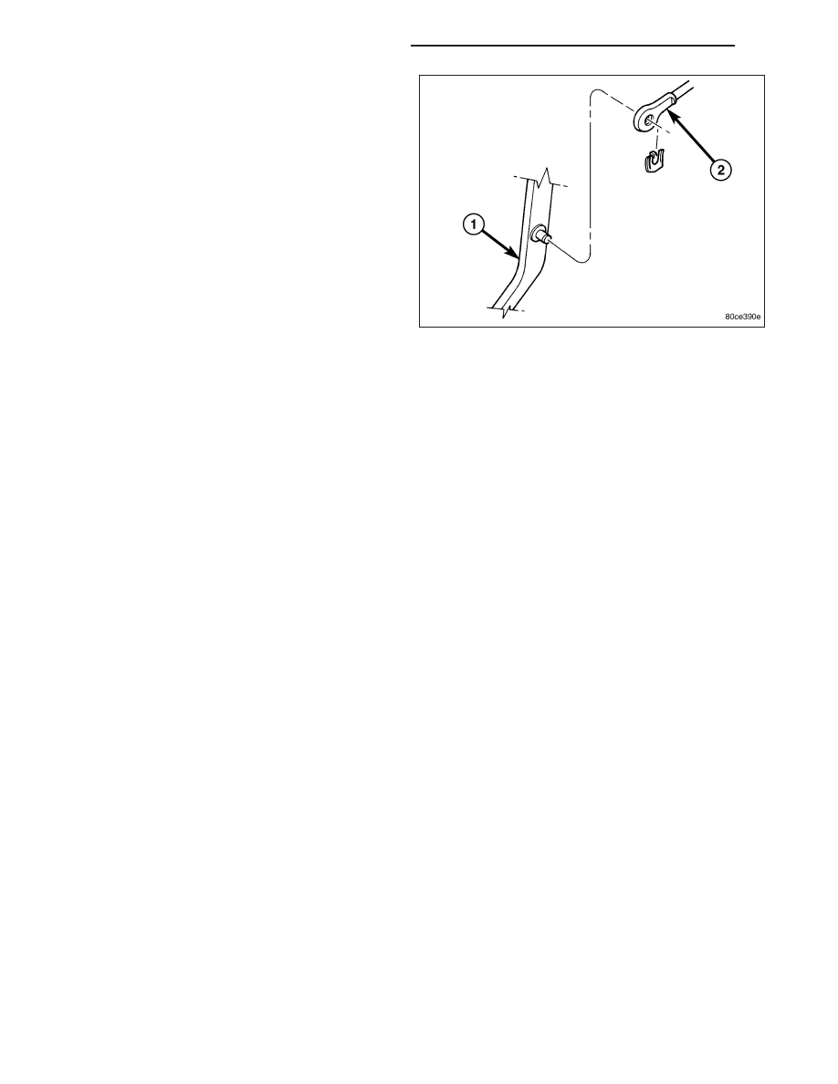
3. Slide booster push rod (2) onto the brake pedal (1).

Then secure push rod (2) to pedal pin with retain-
ing clip.

NOTE: Lubricate the pedal pin with Mopar multi-
mileage grease before installation.

4. Tighten booster mounting nuts to 39 N·m (29 ft.

lbs.).

5. Install a new brake lamp switch and reconnect the

electrical connector.

6. Install the knee blocker, (Refer to 23 - BODY/INSTRUMENT PANEL/KNEE BLOCKER - INSTALLATION).

7. If original master cylinder is being installed, check condition of seal at rear of master cylinder. Replace seal if cut,

or torn.

8. Clean cylinder mounting surface of brake booster. Use shop towel wetted with brake cleaner for this purpose.

Dirt, grease, or similar materials will prevent proper cylinder seating and could result in vacuum leak.

9. Align and install master cylinder on the booster studs. Install mounting nuts and tighten to 17.5 N·m (155 in. lbs.).

10. Connect vacuum hose to booster check valve.

11. Remount the cruise control servo to the original location. Tighten bracket mounting nuts to 17.5 N·m (155 in.

lbs.).

12. Connect and secure the brake lines to HCU and master cylinder. Start all brake line fittings by hand to avoid

cross threading.

13. Connect the wire to fluid reservoir.

14. Install the air box.

15. Fill and bleed base brake system, (Refer to 5 - BRAKES - STANDARD PROCEDURE).

16. Verify proper brake operation before moving vehicle.

5 - 36

BRAKES - BASE - SERVICE INFORMATION

KJ

MASTER CYLINDER

DESCRIPTION

The master cylinder has a removable nylon reservoir. The cylinder body is made of aluminum and contains a pri-
mary and secondary piston assembly. The cylinder body including the piston assemblies are not serviceable. If diag-
nosis indicates an internal problem with the cylinder body, it must be replaced as an assembly. The reservoir and
grommets are the only replaceable parts on the master cylinder.

OPERATION

The master cylinder bore contains a primary and secondary piston. The primary piston supplies hydraulic pressure
to the front brakes. The secondary piston supplies hydraulic pressure to the rear brakes. The master cylinder res-
ervoir stores reserve brake fluid for the hydraulic brake circuits.

DIAGNOSIS AND TESTING - MASTER CYLINDER/POWER BOOSTER

1. Start engine and check booster vacuum hose connections. A hissing noise indicates vacuum leak. Correct any

vacuum leak before proceeding, also ensure booster mounting nuts are torqued correctly.

2. Stop engine and shift transmission into Neutral.

3. Pump brake pedal until all vacuum reserve in booster is depleted.

4. Press and hold brake pedal under light foot pressure. The pedal should hold firm, if the pedal falls away master

cylinder is faulty (internal leakage).

5. Start engine and note pedal action. It should fall away slightly under light foot pressure then hold firm. If no pedal

action is discernible, power booster, vacuum supply, or vacuum check valve is faulty. Proceed to the POWER
BOOSTER VACUUM TEST.

6. If the POWER BOOSTER VACUUM TEST passes, rebuild booster vacuum reserve as follows: Release brake

pedal. Increase engine speed to 1500 rpm, close the throttle and immediately turn off ignition to stop engine.

7. Wait a minimum of 90 seconds and try brake action again. Booster should provide two or more vacuum assisted

pedal applications. If vacuum assist is not provided, booster is faulty.

POWER BOOSTER VACUUM TEST

1. Connect vacuum gauge to booster check valve with short length of hose and T-fitting.

2. Start and run engine at curb idle speed for one minute.

3. Observe the vacuum supply. If vacuum supply is not adequate, repair vacuum supply.

4. Clamp hose shut between vacuum source and check valve.

5. Stop engine and observe vacuum gauge.

KJ

BRAKES - BASE - SERVICE INFORMATION

5 - 37

6. If vacuum drops more than one inch Hg (33 millibars) within 15 seconds, booster diaphragm or check valve is

faulty.

POWER BOOSTER CHECK VALVE TEST

1. Disconnect vacuum hose from check valve.

2. Remove check valve and valve seal from booster.

3. Use a hand operated vacuum pump for test.

4. Apply 15-20 inches vacuum at large end of check

valve.

5. Vacuum should hold steady. If gauge on pump indi-

cates vacuum loss, check valve is faulty and
should be replaced.

STANDARD PROCEDURE - MASTER
CYLINDER BLEEDING

A new master cylinder should be bled before installa-
tion on the vehicle. Required bleeding tools include
bleed tubes and a wood dowel to stroke the pistons.
Bleed tubes can be fabricated from brake line.

1. Mount master cylinder in vise.

2. Attach bleed tubes to cylinder outlet ports. Then

position each tube end into reservoir.

3. Fill reservoir with fresh brake fluid.

4. Press cylinder pistons inward with wood dowel.

Then release pistons and allow them to return under spring pressure. Continue bleeding operations until air bub-
bles are no longer visible in fluid.

5 - 38

BRAKES - BASE - SERVICE INFORMATION

KJ

REMOVAL

1. Siphon and drain the fluid from the reservoir (1).

2. Remove the brake lines at the master cylinder (4).

3. Disconnect the fluid level electrical connector (3)

from the reservoir (1).

4. Remove mounting nuts from the master cylinder

(4).

5. Remove master cylinder (4).

6. Remove cylinder cover and drain the rest of the

fluid.

7. If master cylinder reservoir requires service, (Refer

to 5 - BRAKES/HYDRAULIC/MECHANICAL/FLUID
RESERVOIR - REMOVAL).

INSTALLATION

NOTE: If master cylinder is replaced, bleed cylin-
der before installation.

1. Clean cylinder mounting surface of brake booster

(2).

2. Install master cylinder (4) onto brake booster studs.

3. Install mounting nuts and tighten to 25 N·m (220 in.

lbs.).

4. Connect the brake lines to the master cylinder and

tighten to 20 N·m (180 in. lbs.).

5. Connect fluid level electrical connector (3) to the

reservoir (1).

6. Fill and bleed base brake system, (Refer to 5 -

BRAKES - STANDARD PROCEDURE).

KJ

BRAKES - BASE - SERVICE INFORMATION

5 - 39


Content   ..  567  568  569  570   ..