Jeep Liberty KJ. Manual - part 490


  Index      Jeep     Jeep Liberty KJ - service repair manual 2006 year


Search            


Content   ..  488  489  490  491   ..


Jeep Liberty KJ. Manual - part 490


6.

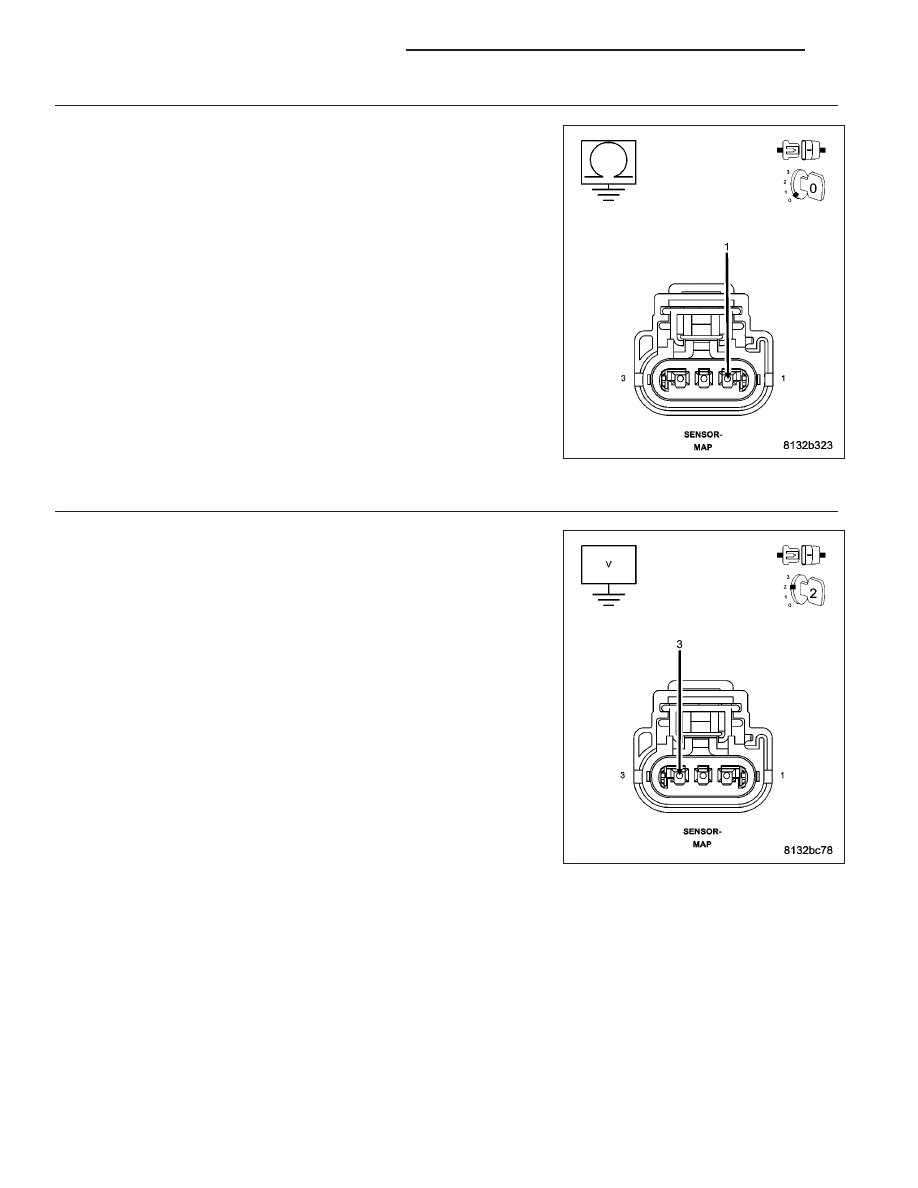
(K1) MAP SIGNAL CIRCUIT SHORTED TO GROUND

Measure the resistance between ground and the (K1) MAP Signal cir-
cuit in the MAP Sensor harness connector.

Is the resistance below 100 ohms?

Yes

>> Repair the short to ground in the (K1) MAP Signal circuit.

Perform the POWERTRAIN VERIFICATION TEST. (Refer to
9 - ENGINE - STANDARD PROCEDURE)

No

>> Go To 10

7.

(F856) 5-VOLT SUPPLY CIRCUIT SHORTED TO BATTERY VOLTAGE

Turn the ignition off.

Disconnect the C1 PCM harness connector.

Ignition on, engine not running.

Measure the voltage on the (F856) 5-volt Supply circuit in the MAP Sen-
sor harness connector.

Is the voltage above 5.2 volts?

Yes

>> Repair the short to battery voltage in the (F856) 5-volt Sup-

ply circuit.

Perform the POWERTRAIN VERIFICATION TEST. (Refer to
9 - ENGINE - STANDARD PROCEDURE)

No

>> Go To 8

9 - 118

ENGINE ELECTRICAL DIAGNOSTICS

KJ

8.

(F856) 5-VOLT SUPPLY CIRCUIT OPEN

Turn the ignition off.

CAUTION: Do not probe the PCM harness connectors. Probing the
PCM harness connectors will damage the PCM terminals resulting
in poor terminal to pin connection. Install Miller Special Tool #8815
to perform diagnosis.
Measure the resistance of the (F856) 5-volt Supply circuit from the MAP
Sensor harness connector to the appropriate terminal of special tool
#8815.

Is the resistance below 5.0 ohms?

Yes

>> Go To 9

No

>> Repair the open in the (F856) 5-volt Supply circuit.

Perform the POWERTRAIN VERIFICATION TEST. (Refer to
9 - ENGINE - STANDARD PROCEDURE)

9.

(F856) 5-VOLT SUPPLY CIRCUIT SHORTED TO GROUND

Measure the resistance between ground and the (F856) 5-volt Supply
circuit in the MAP Sensor harness connector.

Is the resistance below 100 ohms?

Yes

>> Repair the short to ground in the (F856) 5-volt Supply cir-

cuit.

Perform the POWERTRAIN VERIFICATION TEST. (Refer to
9 - ENGINE - STANDARD PROCEDURE)

No

>> Go To 10

KJ

ENGINE ELECTRICAL DIAGNOSTICS

9 - 119

10.

PCM

NOTE: Before continuing, check the PCM harness connector terminals for corrosion, damage, or terminal
push out. Repair as necessary.
Using the schematics as a guide, inspect the wire harness and connectors. Pay particular attention to all Power and
Ground circuits.

Were there any problems found?

Yes

>> Repair as necessary.

Perform the POWERTRAIN VERIFICATION TEST. (Refer to 9 - ENGINE - STANDARD PROCEDURE)

No

>> Replace and program the Powertrain Control Module per Service Information.

Perform the POWERTRAIN VERIFICATION TEST. (Refer to 9 - ENGINE - STANDARD PROCEDURE)

9 - 120

ENGINE ELECTRICAL DIAGNOSTICS

KJ

P0131-O2 SENSOR 1/1 CIRCUIT LOW

For a complete wiring diagram Refer to Section 8W.

KJ

ENGINE ELECTRICAL DIAGNOSTICS

9 - 121


Content   ..  488  489  490  491   ..