Jeep Liberty KJ. Manual - part 489


  Index      Jeep     Jeep Liberty KJ - service repair manual 2006 year


Search            


Content   ..  487  488  489  490   ..


Jeep Liberty KJ. Manual - part 489


12.

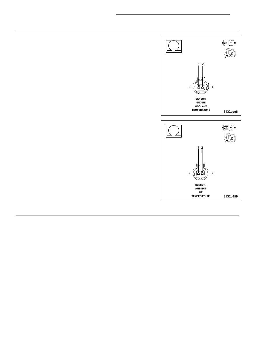
SIGNAL CIRCUIT SHORTED TO THE SENSOR GROUND CIRCUIT

Measure the resistance between the Signal circuit and the (K900) Sen-
sor ground circuit in the (K2) ECT Sensor harness connector.

Measure the resistance between the Signal circuit and the Sensor
ground circuit in the (G31) AAT Sensor harness connector.

Is the resistance below 100 ohms?

Yes

>> Repair the short between the Sensor ground circuit and the

Sensor Signal circuit.

Perform the POWERTRAIN VERIFICATION TEST. (Refer to
9 - ENGINE - STANDARD PROCEDURE)

No

>> Go To 13

13.

PCM

NOTE: Before continuing, check the PCM harness connector terminals for corrosion, damage, or terminal
push out. Repair as necessary.
Using the schematics as a guide, inspect the wire harness and connectors. Pay particular attention to all Power and
Ground circuits.

Were there any problems found?

Yes

>> Repair as necessary.

Perform the POWERTRAIN VERIFICATION TEST. (Refer to 9 - ENGINE - STANDARD PROCEDURE)

No

>> Replace and program the Powertrain Control Module per Service Information.

Perform the POWERTRAIN VERIFICATION TEST. (Refer to 9 - ENGINE - STANDARD PROCEDURE)

9 - 114

ENGINE ELECTRICAL DIAGNOSTICS

KJ

P0129-BAROMETRIC PRESSURE OUT-OF-RANGE LOW

For a complete wiring diagram Refer to Section 8W.

KJ

ENGINE ELECTRICAL DIAGNOSTICS

9 - 115

When Monitored:
With the ignition key on. No Cam or Crank signal within 75 ms. Engine speed less than 250 RPM.

Set Condition:
The PCM senses the voltage from the MAP sensor to be less than 2.2 volts but above 0.04 of a volt for 300
milliseconds. One Trip Fault. Three good trips to turn off the MIL.

Possible Causes

(F856) 5-VOLT SUPPLY CIRCUIT SHORTED TO BATTERY VOLTAGE

(F856) 5-VOLT SUPPLY CIRCUIT OPEN

(F856) 5-VOLT SUPPLY CIRCUIT SHORTED TO GROUND

(K1) MAP SIGNAL CIRCUIT OPEN

(K1) MAP SIGNAL CIRCUIT SHORTED TO GROUND

(K1) MAP SIGNAL CIRCUIT SHORTED TO THE (K900) SENSOR GROUND CIRCUIT

MAP SENSOR

PCM

Always perform the Pre-Diagnostic Troubleshooting procedure before proceeding. (Refer to 9 - ENGINE -
DIAGNOSIS AND TESTING).

Diagnostic Test

1.

ACTIVE DTC

Ignition on, engine not running.

With a scan tool, read DTCs.

Is the DTC active at this time.

Yes

>> Go To 2

No

>> Refer to the INTERMITTENT CONDITION Diagnostic Procedure.

Perform the POWERTRAIN VERIFICATION TEST. (Refer to 9 - ENGINE - STANDARD PROCEDURE)

2.

(F856) 5-VOLT SUPPLY CIRCUIT

Turn the ignition off.

Disconnect the MAP Sensor harness connector.

Ignition on, engine not running.

Measure the voltage on the (F856) 5-volt Supply circuit in the MAP Sen-
sor harness connector.

Is the voltage between 4.5 to 5.2 volts?

Yes

>> Go To 3

No

>> Go To 7

9 - 116

ENGINE ELECTRICAL DIAGNOSTICS

KJ

3.

MAP SENSOR

With a scan tool, monitor the MAP Sensor voltage with the Sensor harness connector disconnected.

Is the voltage above 2.2 volts?

Yes

>> Replace the MAP Sensor.

Perform the POWERTRAIN VERIFICATION TEST. (Refer to 9 - ENGINE - STANDARD PROCEDURE)

No

>> Go To 4

4.

(K1) MAP SIGNAL CIRCUIT OPEN

Turn the ignition off.

Disconnect the C2 PCM harness connector.

CAUTION: Do not probe the PCM harness connectors. Probing the
PCM harness connectors will damage the PCM terminals resulting
in poor terminal to pin connection. Install Miller Special Tool #8815
to perform diagnosis.
Measure the resistance of the (K1) MAP Signal circuit from the MAP
Sensor harness connector to the appropriate terminal of special tool
#8815.

Is the resistance below 5.0 ohms?

Yes

>> Go To 5

No

>> Repair the open in the (K1) MAP Signal circuit.

Perform the POWERTRAIN VERIFICATION TEST. (Refer to
9 - ENGINE - STANDARD PROCEDURE)

5.

(K1) MAP SIGNAL CIRCUIT SHORTED TO THE (K900) SENSOR GROUND CIRCUIT

Measure the resistance between the (K900) Sensor ground circuit and
the (K1) MAP Signal circuit in the MAP Sensor harness connector.

Is the resistance below 5.0 ohms?

Yes

>> Repair the short between the (K900) Sensor ground circuit

and the (K1) MAP Signal circuit.

Perform the POWERTRAIN VERIFICATION TEST. (Refer to
9 - ENGINE - STANDARD PROCEDURE)

No

>> Go To 6

KJ

ENGINE ELECTRICAL DIAGNOSTICS

9 - 117


Content   ..  487  488  489  490   ..