Jeep Liberty KJ. Manual - part 458


  Index      Jeep     Jeep Liberty KJ - service repair manual 2006 year


Search            


Content   ..  456  457  458  459   ..


Jeep Liberty KJ. Manual - part 458


PDC RELAY CASSETTE

REMOVAL

CAUTION: Do not remove the wiring and terminals
from the terminal cavities of the faulty PDC relay
cassette at this time. Refer to the Assembly proce-
dure that follows for the proper procedures for
transferring

the

wiring

and

terminals

to

the

replacement PDC relay cassette.

1. Remove the relay wedge from the PDC relay cas-

sette to be removed.

NOTE: It may be necessary to remove relay cas-
settes that are not being serviced from the PDC
housing in order to obtain sufficient clearance to
access the faulty relay cassette. The same service
procedure is repeated as necessary to remove
each of the interfering relay wedges and relay cas-
settes from the PDC housing.

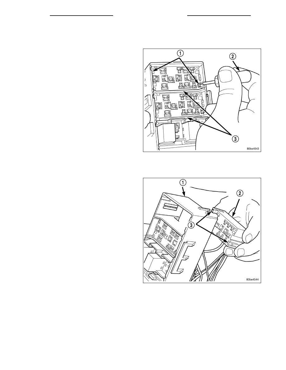
2. From the top of the PDC housing, use a small

screwdriver or a terminal pick tool (2) (Special Tool
Kit 6680) to release the two latches (1) that secure the relay cassette (3) in the PDC.

3. Gently and evenly press the relay cassette (3) down through the PDC housing.

4. From the bottom of the PDC housing (1), remove

the relay cassette (2) from the PDC.

8W - 97 - 12

8W-97 POWER DISTRIBUTION

KJ

ASSEMBLY

POWER DISTRIBUTION CENTER ASSEMBLY

PDC B(+) TERMINAL MODULE

INSTALLATION

1. From the bottom of the PDC housing (1) , align

and insert the B(+) terminal module (3) into the
PDC.

2. From the bottom of the PDC housing (1) , align

and insert the two studs of the PDC B(+) terminal
module (3) through the bus bar (4) in the PDC.

3. From the bottom of the PDC housing (1) , press

the B(+) terminal module (3) gently and evenly into
the PDC until both of the latches (2) are fully
engaged.

4. Install the PDC housing lower cover.

RELAY WEDGE

INSTALLATION

1. From the top of the PDC housing (2), align and

insert the PDC relay wedge (1) latch arms into the
correct cavities in the relay cassette.

2. Gently and evenly press the PDC relay wedge (1)

down into the relay cassette until both of the
latches are fully engaged.

3. Install each of the removed relays into the proper

cavities of the PDC relay wedge (1).

4. Install the PDC housing lower cover.

KJ

8W-97 POWER DISTRIBUTION

8W - 97 - 13

RELAY CASSETTE

INSTALLATION

1. Move the faulty PDC relay cassette with its wiring away from the bottom of the PDC housing far enough to allow

the replacement relay cassette to be installed into the PDC.

2. Using the faulty relay cassette as a guide, be certain that the replacement relay cassette is correctly oriented

before installing it into the PDC housing.

3. From the bottom of the PDC housing, align and insert the replacement relay cassette into the PDC. Press the

relay cassette up into the PDC until both of the latches are fully engaged.

CAUTION: Proper care must be taken to be certain
that the wiring and terminals from the faulty PDC
relay cassette are installed in the correct terminal
cavities of the replacement relay cassette. To pre-
vent mistakes it is recommended that the wiring
and terminals be removed from the faulty relay
cassette one cavity at a time, repaired or spliced
as necessary, then installed securely into the cor-
rect cavity of the replacement relay cassette. If
you are not absolutely certain into which cavity a
terminal should be installed, refer to Power Distri-
bution in the index of this service manual for the
location of complete circuit diagrams covering the
PDC.

4. While pulling gently on the wire from the bottom of

the faulty PDC relay cassette (2), use a terminal
pick tool (4)(Special Tool Kit 6680) from the top of
the relay cassette to release the latch (3) that
secures the terminal in the relay cassette terminal
cavity (1).

5. From the bottom of the faulty PDC relay cassette (2), remove the wire and terminal from the relay cassette

terminal cavity (1).

6. Make all necessary repairs and splices to the wire for the removed terminal. Refer to Wiring Repair in Wiring

Diagrams for the location of the wiring repair procedures.

7. From the bottom of the PDC housing, align and insert the removed wire and terminal into the correct terminal

cavity of the replacement relay cassette. Push the wire and terminal up into the relay cassette terminal cavity
until it is fully engaged by the latch.

8. Repeat Step 4, Step 5, Step 6 and Step 7 one wire and terminal at a time until each of the wires and terminals

have been transferred from the faulty PDC relay cassette into the replacement relay cassette.

9. Install the PDC relay wedge into the replacement PDC relay cassette.

PDC LOWER COVER

INSTALLATION

1. Align the PDC housing lower cover on the bottom of the PDC.

2. Evenly press the lower cover into place until latches are fully engaged.

3. Where the headlamp and dash harness enters the PDC, tape the harness securely to the trough formation on

the PDC lower cover.

4. Install the PDC in its mounting location on the battery support.

5. Install the battery wire harness over the two PDC B+ terminal studs. Torque the nuts to 11.3 N·m (100 in. lbs.).

6. Install the battery. Refer to the Battery section for the procedure.

7. Install the PDC cover.

8W - 97 - 14

8W-97 POWER DISTRIBUTION

KJ

INSTALLATION

The Power Distribution Center (PDC) main housing unit, the PDC fuse wedges, the PDC mini fuse wedge and the
PDC bus bars cannot be repaired and are only serviced as a unit with the right headlamp and dash wire harness.
If the PDC main housing unit, the fuse wedges or the bus bars are faulty or damaged, the entire PDC and right
headlamp and dash wire harness unit must be replaced.

1. Position the PDC and the headlamp and dash wire harness unit in the engine compartment.

2. Engage the PDC housing mounts with the stanchions of the battery tray and push the unit downward until the

mount latches fully engage the mounting tabs on the stanchions.

3. Install the two-holed eyelet of the battery wire harness PDC take outs onto the two PDC B(+) terminal studs.

4. Install and tighten the nuts that secure the eyelet of the battery wire harness PDC take outs to the B(+) terminal

studs. Tighten the nuts to 11.3 N·m (100 in. lbs.).

5. Engage each of the retainers that secure the headlamp and dash wire harness to the vehicle body and chassis

components. Refer to Connector Locations in Wiring Diagrams for the location of more information on the
headlamp and dash wire harness retainer locations.

6. Install all of the fasteners that secure each of the headlamp and dash wire harness ground eyelets to the vehicle

body and chassis components. Refer to Connector Locations in Wiring Diagrams for the location of more infor-
mation on the ground eyelet locations.

7. Reconnect each of the headlamp and dash wire harness connectors. Refer to Connector Locations in Wiring

Diagrams for the location of more information on the headlamp and dash wire harness connector locations. For
connectors secured with bolts, tighten the screws to 4.3 N·m (38 in. lbs.).

8. Reconnect the battery negative cable.

KJ

8W-97 POWER DISTRIBUTION

8W - 97 - 15


Content   ..  456  457  458  459   ..