Jeep Liberty KJ. Manual - part 285


  Index      Jeep     Jeep Liberty KJ - service repair manual 2006 year


Search            


Content   ..  283  284  285  286   ..


Jeep Liberty KJ. Manual - part 285


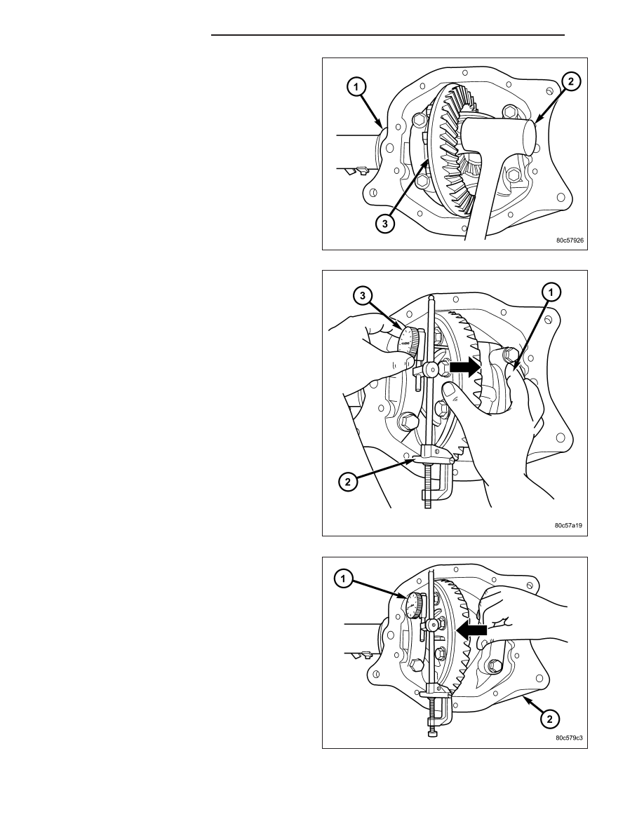
8. With a dead-blow hammer (2), seat differential

dummy bearing to the ring gear (3) side of the
housing (1).

9. Thread Pilot Stud C-3288-B (2) into rear cover bolt

hole below ring gear.

10. Attach a Dial Indicator C-3339 (3) to the Pilot

Stud. Position the dial indicator plunger on flat
surface between the ring gear bolts.

11. Push and hold differential case to pinion gear side

(1) of the housing and zero dial indicator.

12. Push and hold differential case to ring gear side

of the housing (2) and record dial indicator (1)
reading.

13. Add 0.152 mm (0.006 in.) to the zero end play

total. This new total represents the thickness of
shims to compress or preload the new bearings
when the differential is installed.

14. Rotate dial indicator out of the way on the pilot

stud.

15. Remove differential case and dummy bearings

from the housing.

16. Install the pinion gear in the housing. Install the

pinion yoke and establish the correct pinion rotat-
ing torque.

17. Install differential case and Dummy Bearings

D-348 in the housing.

18. Install a single dummy shim in the ring gear side. Install bearing caps and tighten bolts snug.

3 - 44

FRONT AXLE - 186FIA

KJ

19. Seat ring gear side dummy bearing.

20. Position the dial indicator (1) plunger on a flat sur-

face between the ring gear (3) bolt heads.

21. Push and hold differential case toward pinion gear

(2) and zero dial indicator.

22. Push and hold differential case to ring gear side

(3) of the housing and record dial indicator (1)
reading. Add dummy shim thickness to this read-
ing. This will be the total shim thickness to
achieve zero backlash.

23. Subtract 0.076 mm (0.003 in.) from the dial indi-

cator

reading

to

compensate

for

backlash

between ring and pinion gears. This total is the
thickness shim required to achieve proper back-
lash.

24. Subtract the backlash shim thickness from the

total preload shim thickness. The remainder is the
shim thickness required on the pinion side of the
axle housing.

25. Rotate dial indicator out of the way on pilot stud.

26. Remove differential case and dummy bearings

from the housing.

27. Install side bearings and cups on differential case.

28. Install spreader W-129-B with Adapter Set 6987 on the housing and spread axle opening enough to receive

differential case.

CAUTION: Never spread the differential housing over 0.34 mm (0.013 in.). If the housing is over-spread, it
could be distorted or damaged.

29. Place the bearing preload shims in the axle housing, against the axle tubes.

30. Install differential case into the housing.

31. Remove spreader from the housing.

KJ

FRONT AXLE - 186FIA

3 - 45

GEAR BACKLASH

1. Rotate the differential case several times to seat

the side bearings.

2. Position the indicator plunger (1) against a ring

gear tooth (2).

3. Push and hold ring gear upward while not allowing

the pinion gear to rotate.

4. Zero dial indicator face to pointer.

5. Push and hold ring gear downward while not allow-

ing the pinion gear to rotate. Dial indicator reading
should be between 0.12 mm (0.005 in.) and 0.20
mm (0.008 in.). If backlash is not within specifica-
tions transfer the necessary amount of shim thick-
ness from one side of the housing to the other.

6. Verify differential case and ring gear runout by

measuring ring to pinion gear backlash at eight
locations around the ring gear. Readings should
not vary more than 0.05 mm (0.002 in.). If readings vary more than specified, the ring gear or the differential
case is defective.

After the proper backlash is achieved, perform Gear
Contact Pattern Analysis procedure.

3 - 46

FRONT AXLE - 186FIA

KJ

GEAR CONTACT PATTERN

The ring gear and pinion teeth contact patterns will
show if the pinion depth is correct in the housing. It
will also show if the ring gear backlash has been
adjusted correctly. The backlash can be adjusted
within specifications to achieve desired tooth contact
patterns.

The TOP LAND (1) of the gear tooth is the top surface
of the tooth. The PROFILE (2) of the gear tooth is the
depth of the tooth. The TOE (3) of the gear is the por-
tion of the tooth surface at the end towards the center.
The HEEL (4) of the gear is the portion of the tooth at
the outer-end. The ROOT (5) of the gear tooth is the
lowest portion of the tooth.

NOTE: If the PROFILE across the tooth is the same it is a 3 Axis cut gear. If the PROFILE across the tooth
is tapered it is a 2 Axis cut gear.

1. Apply a thin coat of hydrated ferric oxide or equivalent to the drive and coast side of the ring gear teeth.

2. Wrap, twist and hold a shop towel around the pinion yoke to increase the turning resistance of the pinion. This

will provide a more distinct contact pattern.

3. With a boxed end wrench on a ring gear bolt, rotate the differential case one complete revolution in both direc-

tions while a load is being applied from shop towel.

The areas on the ring gear teeth with the greatest degree of contact against the pinion teeth will squeegee the
compound to the areas with the least amount of contact. Note and compare patterns on the ring gear teeth to Gear
Tooth Contact Patterns chart and adjust pinion depth and gear backlash as necessary.

KJ

FRONT AXLE - 186FIA

3 - 47


Content   ..  283  284  285  286   ..