Jeep Liberty KJ. Manual - part 242


  Index      Jeep     Jeep Liberty KJ - service repair manual 2006 year


Search            


Content   ..  240  241  242  243   ..


Jeep Liberty KJ. Manual - part 242


1. Disconnect and isolate the battery negative cable. Wait two minutes for the system capacitor to discharge before

further service.

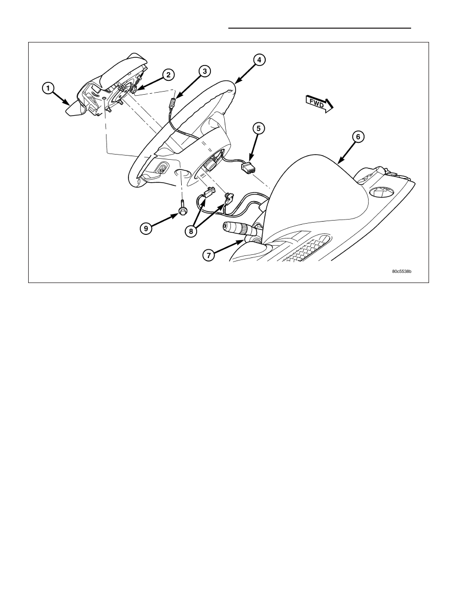
2. From the underside of the steering wheel, remove the two screws (9) that secure the driver airbag (1) to the

steering wheel armature.

3. Pull the driver airbag away from the steering wheel (4) far enough to access the three electrical connections on

the back of the airbag housing.

4. Disconnect the steering wheel wire harness connector (3) for the horn switch from the horn switch feed pigtail

wire connector (2), which is located on the back of the driver airbag housing.

CAUTION: Do not pull on the clockspring pigtail wires or pry on the connector insulator to disengage the
connector from the driver airbag inflator connector receptacle. Improper removal of these pigtail wires and
their connector insulators can result in damage to the airbag circuits or connector insulators.

5. The clockspring driver airbag pigtail wire connectors (8) are secured by integral latches to the airbag inflator

connector receptacles, which are located on the back of the driver airbag housing. Depress the latches on each
side of each connector insulator and pull the insulators straight out from the airbag inflator to disconnect them
from the connector receptacles.

6. Remove the driver airbag from the steering wheel.

7. If the driver airbag has been deployed, the clockspring must be replaced. (Refer to 8 - ELECTRICAL/RE-

STRAINTS/CLOCKSPRING - REMOVAL).

INSTALLATION

WARNING: To avoid personal injury or death, on vehicles equipped with airbags, disable the supplemental
restraint system before attempting any steering wheel, steering column, airbag, occupant classification sys-
tem, seat belt tensioner, impact sensor, or instrument panel component diagnosis or service. Disconnect
and isolate the battery negative (ground) cable, then wait two minutes for the system capacitor to discharge
before performing further diagnosis or service. This is the only sure way to disable the supplemental
restraint system. Failure to take the proper precautions could result in accidental airbag deployment.

8O - 274

RESTRAINTS - SERVICE INFORMATION

KJ

WARNING: To avoid personal injury or death, use extreme care to prevent any foreign material from enter-
ing the driver airbag, or becoming entrapped between the driver airbag cushion and the driver airbag trim
cover. Failure to observe this warning could result in occupant injuries upon airbag deployment.

WARNING: To avoid personal injury or death, the driver airbag trim cover must never be painted. Replace-
ment airbags are serviced with trim covers in the original colors. Paint may change the way in which the
material of the trim cover responds to an airbag deployment. Failure to observe this warning could result in
occupant injuries upon airbag deployment.

NOTE: The following procedure is for replacement of a faulty or damaged driver airbag. If the airbag is
faulty or damaged, but not deployed, review the recommended procedures for handling non-deployed sup-
plemental restraints. (Refer to 8 - ELECTRICAL/RESTRAINTS - STANDARD PROCEDURE - HANDLING NON-
DEPLOYED

SUPPLEMENTAL

RESTRAINTS).

If

the

driver

airbag

has

been

deployed,

review

the

recommended procedures for service after a supplemental restraint deployment before removing the airbag
from the vehicle. (Refer to 8 - ELECTRICAL/RESTRAINTS - STANDARD PROCEDURE - SERVICE AFTER A
SUPPLEMENTAL RESTRAINT DEPLOYMENT).

1. Position the driver airbag (1) close enough to the steering wheel (4) to reconnect the three electrical connections

on the back of the airbag housing.

2. When installing the driver airbag, reconnect the two clockspring driver airbag pigtail wire connectors (8) to the

airbag inflator connector receptacles by pressing straight in on the connectors. Be certain to engage each keyed
and color-coded connector to the matching connector receptacle. You can be certain that each connector is fully
engaged in its receptacle by listening carefully for a distinct, audible click as the connector latches snap into
place.

3. Reconnect the steering wheel wire harness connector (3) for the horn switch to the horn switch feed pigtail wire

connector (2), which is located at the back of the driver airbag housing.

4. Carefully position the driver airbag in the steering wheel. Be certain that the clockspring pigtail wires and steering

wheel wire harness in the steering wheel hub area are not pinched between the driver airbag and the steering
wheel armature.

KJ

RESTRAINTS - SERVICE INFORMATION

8O - 275

5. From the underside of the steering wheel, install and tighten the two screws (9) that secure the driver airbag to

the steering wheel armature. Tighten the screws to 10 N·m (90 in. lbs.).

6. Do not reconnect the battery negative cable at this time. The supplemental restraint system verification test pro-

cedure should be performed following service of any supplemental restraint system component. (Refer to 8 -
ELECTRICAL/RESTRAINTS - STANDARD PROCEDURE - VERIFICATION TEST).

8O - 276

RESTRAINTS - SERVICE INFORMATION

KJ

IMPACT SENSOR

DESCRIPTION

FRONT

Two front impact sensors (1) are used on this model,
one each for the left and right sides of the vehicle.
These sensors are mounted remotely from the impact
sensor that is internal to the Airbag Control Module
(ACM). Each front sensor is secured with a screw to
the backs of the right and left vertical members of the
radiator support within the engine compartment. The
sensor housing has an integral connector receptacle
(4), an integral anti-rotation pin (3), and an integral
mounting hole (2) with a metal sleeve to provide crush
protection.

The right and left front impact sensors are identical in construction and calibration. A cavity in the center of the
molded black plastic impact sensor housing contains the electronic circuitry of the sensor which includes an elec-
tronic communication chip and an electronic impact sensor. Potting material fills the cavity to seal and protect the
internal electronic circuitry and components. The front impact sensors are each connected to the vehicle electrical
system through a dedicated take out and connector of the headlamp and dash wire harness.

The impact sensors cannot be repaired or adjusted and, if damaged or faulty, they must be replaced.

SIDE

Two side impact sensors (1) are used on this model
when it is equipped with the optional side curtain air-
bags, one each for the left and right sides of the vehi-
cle. These sensors are mounted remotely from the
impact sensor that is internal to the Airbag Control
Module (ACM). Each side sensor is secured with a
screw to the inner right or left B-pillar above the front
seat belt retractor within the passenger compartment.
The sensor housing has an integral connector recep-
tacle (4), an integral anti-rotation pin (3), and an inte-
gral mounting hole (2) with a metal sleeve to provide
crush protection.

The right and left side impact sensors are identical in construction and calibration. A cavity in the center of the
molded black plastic impact sensor housing contains the electronic circuitry of the sensor which includes an elec-
tronic communication chip and an electronic impact sensor. Potting material fills the cavity to seal and protect the
internal electronic circuitry and components. The side impact sensors are each connected to the vehicle electrical
system through a dedicated take out and connector of the body wire harness.

The impact sensors cannot be repaired or adjusted and, if damaged or faulty, they must be replaced.

KJ

RESTRAINTS - SERVICE INFORMATION

8O - 277


Content   ..  240  241  242  243   ..