Jeep Liberty KJ. Manual - part 241


  Index      Jeep     Jeep Liberty KJ - service repair manual 2006 year


Search            


Content   ..  239  240  241  242   ..


Jeep Liberty KJ. Manual - part 241


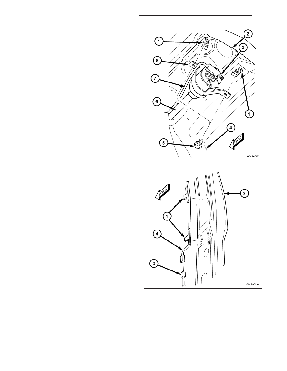
3. Install and tighten the upper screw (5) that secures

the side curtain airbag inflator bracket (8) to the
U-nut (1) in the roof rail, followed by the lower
screw. Tighten the screws to 12 N·m (105 in. lbs.).

4. Working from the rear of the vehicle to the front,

install and tighten each of the three screws that
secure the side curtain airbag manifold tube brack-
ets to the U-nuts in the roof rail. Tighten the screws
to 12 N·m (105 in. lbs.).

5. Route the side curtain airbag pigtail wire (4)

through the trough along the top of the extruded
plastic airbag channel on the roof side rail, then
between the channel and the body down the B-pil-
lar (2).

NOTE: Be certain that the side curtain airbag pig-
tail wire is routed behind the airbag channel,
between the channel and the body above the B-pil-
lar.

6. Engage the three side curtain airbag pigtail wire

retainer clips (1) into the B-pillar.

7. Reconnect the side curtain airbag pigtail wire con-

nector to the body wire harness connector (3) near
the base of the B-pillar.

8O - 270

RESTRAINTS - SERVICE INFORMATION

KJ

8. Engage the side curtain airbag tether (3) plastic

retainer clip (2) into the A-pillar (1).

9. Install and tighten the screw (5) that secures the

side curtain airbag tether retainer (4) to the base of
the A-pillar near the belt line. Tighten the screw to
14 N·m (120 in. lbs.).

10. Reinstall the headliner into the vehicle. (Refer to

23 - BODY/INTERIOR/HEADLINER - INSTALLA-
TION).

11. Reinstall the lower trim onto the inside of the

B-pillar. (Refer to 23 - BODY/INTERIOR/B-PILLAR
LOWER TRIM - INSTALLATION).

12. Do not reconnect the battery negative cable at

this time. The supplemental restraint system veri-
fication test procedure should be performed fol-
lowing

service

of

any

supplemental

restraint

system component. (Refer to 8 - ELECTRICAL/
RESTRAINTS

-

STANDARD

PROCEDURE

-

VERIFICATION TEST).

KJ

RESTRAINTS - SERVICE INFORMATION

8O - 271

DRIVER AIRBAG

DESCRIPTION

The black, injection molded, thermoplastic driver air-
bag protective trim cover (2) is the most visible part of
the driver airbag. The driver airbag is located in the
center of the steering wheel (1), where it is secured
with two screws to the two horizontal spokes of the
four-spoke steering wheel armature. All models have a
bright silver Jeep

T

logo applied to the center of the

trim cover. Concealed beneath the driver airbag trim
cover are the horn switch, the folded airbag cushion,
the airbag cushion retainer, the airbag housing, the
airbag inflator, and the retainers that secure the infla-
tor to the airbag housing. The airbag cushion, housing,
and inflator are secured within an integral receptacle
molded into the back of the trim cover.

The resistive membrane-type horn switch is secured
with heat stakes to the inside surface of the driver air-
bag trim cover (5), between the trim cover and the
folded airbag cushion. The horn switch ground pigtail
wire (2) has a female spade terminal connector that
receives a path to ground through a male spade ter-
minal that is integral to the driver airbag housing
stamping (1) and is located near the upper right cor-
ner on the back of the housing. The horn switch feed
pigtail wire (3) has a white, molded plastic insulator
that is secured by an integral retainer to a mounting
hole located near the lower left corner on the back of
the housing, and is connected to the vehicle electrical
system through a take out and connector of the steer-
ing wheel wire harness.

The airbag used in this model is a multistage unit that complies with revised federal airbag standards to deploy with
less force than those used in some prior models. A 71 centimeter (28.0 inch) diameter, radial deploying fabric cush-
ion with internal tethers is used. The airbag inflator (4) is a dual-initiator, non-azide, pyrotechnic-type unit with four
mounting studs and is secured to the stamped metal airbag housing using four hex nuts with washers. Two keyed
and color-coded connector receptacles on the driver airbag inflator connect the two inflator initiators to the vehicle
electrical system through two yellow or black-jacketed, two-wire pigtail harnesses of the clockspring.

The driver airbag unit cannot be repaired, and must be replaced if deployed or in any way damaged.

OPERATION

The multistage driver airbag is deployed by electrical signals generated by the Airbag Control Module (ACM)
through the driver airbag squib 1 and squib 2 circuits to the two initiators in the airbag inflator. By using two initi-
ators, the airbag can be deployed at multiple levels of force. The force level is controlled by the ACM to suit the
monitored impact conditions by providing one of three delay intervals between the electrical signals provided to the
two initiators. The longer the delay between these signals, the less forcefully the airbag will deploy.

When the ACM sends the proper electrical signals to each initiator, the electrical energy generates enough heat to
initiate a small pyrotechnic charge which, in turn ignites chemical pellets within the inflator. Once ignited, these
chemical pellets burn rapidly and produce a large quantity of inert gas. The inflator is sealed to the back of the
airbag housing and a diffuser in the inflator directs all of the inert gas into the airbag cushion, causing the cushion
to inflate. As the cushion inflates, the driver airbag trim cover will split at predetermined breakout lines, then fold
back out of the way along with the horn switch unit. Following an airbag deployment, the airbag cushion quickly

8O - 272

RESTRAINTS - SERVICE INFORMATION

KJ

deflates by venting the inert gas towards the instrument panel through vent holes within the fabric used to construct
the back (steering wheel side) panel of the airbag cushion.

Some of the chemicals used to create the inert gas may be considered hazardous while in their solid state before
they are burned, but they are securely sealed within the airbag inflator. Typically, both initiators are used and all
potentially hazardous chemicals are burned during an airbag deployment event. However, it is possible for only one
initiator to be used during a deployment due to an airbag system fault; therefore, it is necessary to always confirm
that both initiators have been used in order to avoid the improper disposal of potentially live pyrotechnic or hazard-
ous materials. (Refer to 8 - ELECTRICAL/RESTRAINTS - STANDARD PROCEDURE - SERVICE AFTER A SUP-
PLEMENTAL RESTRAINT DEPLOYMENT).

The inert gas that is produced when the chemicals are burned is harmless. However, a small amount of residue
from the burned chemicals may cause some temporary discomfort if it contacts the skin, eyes, or breathing pas-
sages. If skin or eye irritation is noted, rinse the affected area with plenty of cool, clean water. If breathing passages
are irritated, move to another area where there is plenty of clean, fresh air to breath. If the irritation is not alleviated
by these actions, contact a physician.

REMOVAL

WARNING: To avoid personal injury or death, on vehicles equipped with airbags, disable the supplemental
restraint system before attempting any steering wheel, steering column, airbag, occupant classification sys-
tem, seat belt tensioner, impact sensor, or instrument panel component diagnosis or service. Disconnect
and isolate the battery negative (ground) cable, then wait two minutes for the system capacitor to discharge
before performing further diagnosis or service. This is the only sure way to disable the supplemental
restraint system. Failure to take the proper precautions could result in accidental airbag deployment.

WARNING: To avoid personal injury or death, when removing a deployed airbag, rubber gloves, eye protec-
tion, and a long-sleeved shirt should be worn. There may be deposits on the airbag cushion and other inte-
rior surfaces. In large doses, these deposits may cause irritation to the skin and eyes.

NOTE: The following procedure is for replacement of a faulty or damaged driver airbag. If the airbag is
faulty or damaged, but not deployed, review the recommended procedures for handling non-deployed sup-
plemental restraints. (Refer to 8 - ELECTRICAL/RESTRAINTS - STANDARD PROCEDURE - HANDLING NON-
DEPLOYED

SUPPLEMENTAL

RESTRAINTS).

If

the

driver

airbag

has

been

deployed,

review

the

recommended procedures for service after a supplemental restraint deployment before removing the airbag
from the vehicle. (Refer to 8 - ELECTRICAL/RESTRAINTS - STANDARD PROCEDURE - SERVICE AFTER A
SUPPLEMENTAL RESTRAINT DEPLOYMENT).

KJ

RESTRAINTS - SERVICE INFORMATION

8O - 273


Content   ..  239  240  241  242   ..