Jeep Liberty KJ. Manual - part 75


  Index      Jeep     Jeep Liberty KJ - service repair manual 2006 year


Search            


Content   ..  73  74  75  76   ..


Jeep Liberty KJ. Manual - part 75


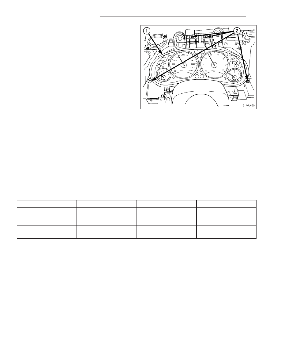
1. Position the instrument cluster (1) close enough to

the instrument panel to reconnect the instrument
panel wire harness connector to the connector
receptacle on the back of the cluster housing.

2. Position the instrument cluster into the instrument

panel.

3. Install and tighten the four screws (2) that secure

the instrument cluster to the instrument panel.
Tighten the screws to 2 N·m (17 in. lbs.).

4. Reinstall the cluster bezel onto the instrument

panel. (Refer to 23 - BODY/INSTRUMENT PANEL/
CLUSTER BEZEL - INSTALLATION).

5. Reconnect the battery negative cable.

NOTE: If the instrument cluster has been replaced,
certain indicators in this instrument cluster will be automatically configured when the cluster is connected
to the electrical system of the vehicle. This feature allows those indicators to be activated for compatibility
with certain optional equipment. Some other indicators may require manual intervention to obtain proper
configuration for the equipment in the specific vehicle. If a problem is noted involving erroneous illumina-
tion of the ABS indicator, the airbag indicator, the electronic throttle control indicator, the Part Time indi-
cator or the Full Time indicator when the vehicle does not have the appropriate equipment, a diagnostic
scan tool must be used to manually enable or disable the correct indicator(s). Refer to the appropriate diag-
nostic information.

SPECIFICATIONS

INSTRUMENT CLUSTER

TORQUE SPECIFICATIONS

DESCRIPTION

N·m

Ft. Lbs.

In. Lbs.

Instrument Cluster Lens,

Hood and Mask Mounting

Screws

1

-

10

Instrument Cluster

Mounting Screws

2

-

17

8J - 106

INSTRUMENT CLUSTER

KJ

ABS INDICATOR

DESCRIPTION

An Antilock Brake System (ABS) indicator is standard
equipment on all instrument clusters. However, on
vehicles not equipped with the optional ABS, this indi-
cator is electronically disabled. This indicator is
located above the engine temperature gauge and to the right of the tachometer in the cluster overlay.

The ABS indicator consists of a stencil-like cutout of the International Control and Display Symbol icon for “Failure
of Anti-lock Braking System” in the opaque layer of the instrument cluster overlay. The dark outer layer of the over-
lay prevents the indicator from being clearly visible when it is not illuminated. An amber Light Emitting Diode (LED)
behind the cutout in the opaque layer of the overlay causes the icon to appear in amber through the translucent
outer layer of the overlay when the indicator is illuminated from behind by the LED, which is soldered onto the
instrument cluster electronic circuit board.

The ABS indicator is serviced as a unit with the instrument cluster.

OPERATION

The ABS indicator gives an indication to the vehicle operator when the ABS system is faulty or inoperative. This
indicator is controlled by a transistor on the instrument cluster circuit board based upon cluster programming and
electronic messages received by the cluster from the Controller Antilock Brake (CAB) over the Programmable Com-
munications Interface (PCI) data bus.

The ABS indicator Light Emitting Diode (LED) is completely controlled by the instrument cluster logic circuit, and that
logic will only allow this indicator to operate when the instrument cluster receives a battery current input on the
fused ignition switch output (run-start) circuit. Therefore, the LED will always be off when the ignition switch is in any
position except On or Start. The LED only illuminates when it is provided a path to ground by the instrument cluster
transistor. The instrument cluster will turn on the ABS indicator for the following reasons:

Bulb Test - Each time the ignition switch is turned to the On position the ABS indicator is illuminated by the
instrument cluster for about three seconds as a bulb test.

ABS Lamp-On Message - Each time the cluster receives a lamp-on message from the CAB, the ABS indi-
cator will be illuminated. The indicator remains illuminated until the cluster receives a lamp-off message from
the CAB, or until the ignition switch is turned to the Off position, whichever occurs first.

Communication Error - If the cluster receives no lamp-on or lamp-off messages from the CAB for six con-
secutive seconds, the ABS indicator is illuminated. The indicator remains illuminated until the cluster receives
a valid message from the CAB, or until the ignition switch is turned to the Off position, whichever occurs first.

Actuator Test - Each time the instrument cluster is put through the actuator test, the ABS indicator will be
turned on, then off again during the bulb check portion of the test to confirm the functionality of the LED and
the cluster control circuitry.

ABS Diagnostic Test - The ABS indicator is blinked on and off by lamp-on and lamp-off messages from the
CAB during the performance of the ABS diagnostic tests.

The CAB continually monitors the ABS circuits and sensors to decide whether the system is in good operating con-
dition. The CAB then sends the proper lamp-on or lamp-off messages to the instrument cluster. If the CAB sends a
lamp-on message after the bulb test, it indicates that the CAB has detected a system malfunction and/or that the
ABS system has become inoperative. The CAB will store a Diagnostic Trouble Code (DTC) for any malfunction it
detects. Each time the ABS indicator fails to light due to an open or short in the cluster ABS indicator circuit, the
cluster sends a message notifying the CAB of the condition, then the instrument cluster and the CAB will each store
a DTC.

For proper diagnosis of the antilock brake system, the CAB, the PCI data bus, or the electronic message inputs to
the instrument cluster that control the ABS indicator, a diagnostic scan tool is required. Refer to the appropriate
diagnostic information.

KJ

INSTRUMENT CLUSTER

8J - 107

AIRBAG INDICATOR

DESCRIPTION

An airbag indicator is standard equipment on all
instrument clusters. However, the instrument cluster is
programmed to automatically enable this indicator only
on vehicles equipped with the airbag system, which is
not available in some markets. The indicator is located above the fuel gauge and to the left of the speedometer in
the instrument cluster overlay.

The airbag indicator consists of a stencil-like cutout of the text “AIR BAG” in the opaque layer of the instrument
cluster overlay. The dark outer layer of the overlay prevents the indicator from being clearly visible when it is not
illuminated. A red Light Emitting Diode (LED) behind the cutout in the opaque layer of the overlay causes the “AIR
BAG” text to appear in red through the translucent outer layer of the overlay when the indicator is illuminated from
behind by the LED, which is soldered onto the instrument cluster electronic circuit board.

The airbag indicator is serviced as a unit with the instrument cluster.

OPERATION

The airbag indicator gives an indication to the vehicle operator when the airbag system is faulty or inoperative. The
airbag indicator is controlled by a transistor on the instrument cluster circuit board based upon cluster programming
and electronic messages received by the cluster from the Airbag Control Module (ACM) over the Programmable
Communications Interface (PCI) data bus.

The airbag indicator Light Emitting Diode (LED) is completely controlled by the instrument cluster logic circuit, and
that logic will only allow this indicator to operate when the instrument cluster receives a battery current input on the
fused ignition switch output (run-start) circuit. Therefore, the LED will always be off when the ignition switch is in any
position except On or Start. The LED only illuminates when it is provided a path to ground by the instrument cluster
transistor. The instrument cluster will turn on the airbag indicator for the following reasons:

Bulb Test - Each time the ignition switch is turned to the On position the airbag indicator is illuminated for
about six seconds. The entire bulb test is a function of the ACM.

ACM Lamp-On Message - Each time the cluster receives a lamp-on message from the ACM, the airbag indi-
cator will be illuminated. The indicator remains illuminated for about 12 seconds or until the cluster receives a
lamp-off message from the ACM, whichever is longer.

Communication Error - If the cluster receives no airbag messages for six consecutive seconds, the airbag
indicator is illuminated. The indicator remains illuminated until the cluster receives a single lamp-off message
from the ACM.

Actuator Test - Each time the cluster is put through the actuator test, the airbag indicator will be turned on,
then off again during the bulb check portion of the test to confirm the functionality of the LED and the cluster
control circuitry. The actuator test illumination of the airbag indicator is a function of the instrument cluster.

The ACM continually monitors the airbag system circuits and sensors to decide whether the system is in good oper-
ating condition. The ACM then sends the proper lamp-on or lamp-off messages to the instrument cluster. If the ACM
sends a lamp-on message after the bulb test, it indicates that the ACM has detected a system malfunction and/or
that the airbags and seat belt tensioners may not deploy when required, or may deploy when not required. The
ACM will store a Diagnostic Trouble Code (DTC) for any malfunction it detects. Each time the airbag indicator fails
to illuminate due to an open or short in the cluster airbag indicator circuit, the cluster sends a message notifying the
ACM of the condition, then the instrument cluster and the ACM will each store a DTC.

For proper diagnosis of the airbag system, the ACM, the PCI data bus, or the electronic message inputs to the
instrument cluster that control the airbag indicator, a diagnostic scan tool is required. Refer to the appropriate diag-
nostic information.

8J - 108

INSTRUMENT CLUSTER

KJ

BRAKE/PARK BRAKE INDICATOR

DESCRIPTION

A brake indicator is standard equipment on all instru-
ment clusters. This indicator is located near the lower
edge of the speedometer gauge dial face in the instru-
ment cluster overlay.

The brake indicator consists of stencil-like cutout of the text “BRAKE” and the International Control and Display
Symbol icon for “Brake Failure” in the opaque layer of the instrument cluster overlay. The dark outer layer of the
overlay prevents the indicator from being clearly visible when it is not illuminated. A red Light Emitting Diode (LED)
behind the cutout in the opaque layer of the overlay causes the text and icon to appear in red through the trans-
lucent outer layer of the overlay when the indicator is illuminated from behind by the LED, which is soldered onto
the instrument cluster electronic circuit board.

The brake indicator is serviced as a unit with the instrument cluster.

OPERATION

The brake indicator gives an indication to the vehicle operator when the parking brake is applied, when there are
certain brake hydraulic system malfunctions as indicated by a low brake hydraulic fluid level condition, or when the
brake fluid level switch is disconnected. On models equipped with an optional Antilock Brake System (ABS), the
brake indicator can also give an indication when certain faults are detected in the ABS. This indicator is controlled
by a transistor on the instrument cluster circuit board based upon cluster programming, electronic messages
received by the cluster from the Controller Antilock Brake (CAB) over the Programmable Communications Interface
(PCI) data bus (ABS only), and hard wired inputs from the park brake switch and the brake fluid level switch.

The brake indicator Light Emitting Diode (LED) is completely controlled by the instrument cluster logic circuit, and
that logic will only allow this indicator to operate when the instrument cluster receives a battery current input on the
fused ignition switch output (run-start) circuit. Therefore, the LED will always be off when the ignition switch is in any
position except On or Start. The LED only illuminates when it is provided a path to ground by the instrument cluster
transistor. The instrument cluster will turn on the brake indicator for the following reasons:

Bulb Test - Each time the ignition switch is turned to the On position the brake indicator is illuminated by the
instrument cluster for about three seconds as a bulb test.

Brake Lamp-On Message - Each time the cluster receives a lamp-on message from the CAB, the brake indi-
cator will be illuminated. The indicator remains illuminated until the cluster receives a lamp-off message from
the CAB, or until the ignition switch is turned to the Off position, whichever occurs first.

Park Brake Switch Input - Each time the cluster detects ground on the park brake switch sense circuit (park
brake switch closed = park brake applied or not fully released) while the ignition switch is in the On position,
the brake indicator is illuminated. The indicator remains illuminated until the park brake switch sense input to
the cluster is an open circuit (park brake switch open = park brake fully released), or until the ignition switch
is turned to the Off position, whichever occurs first.

Brake Fluid Level Switch Input - Each time the cluster detects ground on the red brake warning indicator
driver circuit (brake fluid level switch closed = brake hydraulic system fluid level low) while the ignition switch
is in the On position, the brake indicator is illuminated. The indicator remains illuminated until the status of the
red brake warning indicator driver input to the cluster is off (brake fluid level switch off = brake hydraulic sys-
tem fluid level is not low), or until the ignition switch is turned to the Off position, whichever occurs first.

Brake Fluid Level Switch Input Fault - The brake fluid level switch also features a 1 kilohm diagnostic resis-
tor connected in parallel between the switch input and output to provide the cluster with verification that the red
brake warning indicator driver circuit is not open. If the cluster does not see a proper input on the red brake
warning indicator driver circuit while the ignition switch is in the On position, it will turn on the brake indicator.
The indicator remains illuminated until the red brake warning indicator driver circuit fault is resolved, or until the
ignition switch is turned to the Off position, whichever occurs first.

Actuator Test - Each time the instrument cluster is put through the actuator test, the brake indicator will be
turned on, then off again during the bulb check portion of the test to confirm the functionality of the LED and
the cluster control circuitry.

The park brake switch on the park brake lever mechanism provides a hard wired ground input to the instrument
cluster circuitry through the park brake switch sense circuit whenever the park brake is applied or not fully released.

KJ

INSTRUMENT CLUSTER

8J - 109


Content   ..  73  74  75  76   ..