Jeep Grand Cherokee WK. Manual - part 400


  Index      Jeep     Jeep Grand Cherokee WK - service repair manual 2005 year


Search            


Content   ..  398  399  400  401   ..


Jeep Grand Cherokee WK. Manual - part 400


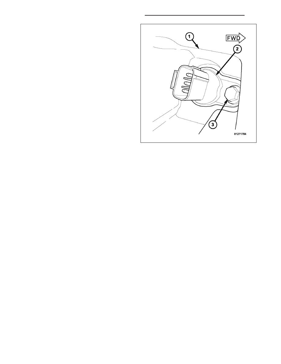
2. Remove sensor mounting bolt (3).

3. Carefully twist sensor (2) from cylinder head.

4. Check condition of sensor o-ring.

INSTALLATION

3.7L V-6

1. Clean out machined hole in cylinder head.

2. Apply a small amount of engine oil to sensor o-ring.

3. Install sensor into cylinder head with a slight rocking and twisting action.

CAUTION: Before tightening sensor mounting bolt, be sure sensor is completely flush to cylinder head. If
sensor is not flush, damage to sensor mounting tang may result.

4. Install mounting bolt and tighten. Refer to torque specifications.

5. Connect electrical connector to sensor.

4.7L V-8

1. Clean out machined hole in cylinder head.

2. Apply a small amount of engine oil to sensor o-ring.

3. Install sensor into cylinder head with a slight rocking action. Do not twist sensor into position as damage to o-ring

may result.

CAUTION: Before tightening sensor mounting bolt, be sure sensor is completely flush to cylinder head. If
sensor is not flush, damage to sensor mounting tang may result.

4. Install mounting bolt and tighten. Refer to Torque Specifications.

5. Connect electrical connector to sensor.

5.7L V-8

1. Clean out machined hole in cylinder head.

2. Apply a small amount of engine oil to sensor o-ring.

3. Install sensor into cylinder head with a slight rocking action. Do not twist sensor into position as damage to o-ring

may result.

CAUTION: Before tightening sensor mounting bolt, be sure sensor is completely flush to timing chain cover.
If sensor is not flush, damage to sensor mounting tang may result.

4. Install mounting bolt and tighten. Refer to Torque Specifications.

5. Connect electrical connector to sensor.

8I - 20

IGNITION SYSTEM - SERVICE INFORMATION

WK

COIL-IGNITION

DESCRIPTION

3.7L V-6

The 3.7L V-6 engine uses 6 dedicated, and individu-
ally fired coil for each spark plug (2).

Each coil (1) is mounted directly into the cylinder head
and onto the top of each spark plug.

WK

IGNITION SYSTEM - SERVICE INFORMATION

8I - 21

4.7L V-8

The 4.7L V–8 engine uses 8 dedicated, and individu-
ally fired coil (1) for each spark plug. Each coil is
mounted directly to the top of each spark plug.

5.7L V-8

The 5.7L V–8 engine uses 8 dedicated, and individu-
ally fired coil (1) for each pair of spark plugs.

8I - 22

IGNITION SYSTEM - SERVICE INFORMATION

WK

Each coil (5) is mounted directly to the top of each
spark plug. Each coil is bolted (6) to the valve cover.

OPERATION

3.7L V-6

Battery voltage is supplied to the 6 individual ignition coils from the ASD relay. The Powertrain Control Module
(PCM) opens and closes each ignition coil ground circuit at a determined time for ignition coil operation.

Base ignition timing is not adjustable. By controlling the coil ground circuit, the PCM is able to set the base
timing and adjust the ignition timing advance. This is done to meet changing engine operating conditions.

The ignition coil is not oil filled. The windings are embedded in an epoxy compound. This provides heat and vibra-
tion resistance that allows the ignition coil to be mounted on the engine.

Because of coil design, spark plug cables (secondary cables) are not used with the 3.7L V-6 engine.

4.7L V-8

Battery voltage is supplied to the 8 individual ignition coils from the ASD relay. The Powertrain Control Module
(PCM) opens and closes each ignition coil ground circuit at a determined time for ignition coil operation.

Base ignition timing is not adjustable. By controlling the coil ground circuit, the PCM is able to set the base
timing and adjust the ignition timing advance. This is done to meet changing engine operating conditions.

The ignition coil is not oil filled. The windings are embedded in an epoxy compound. This provides heat and vibra-
tion resistance that allows the ignition coil to be mounted on the engine.

Because of coil design, spark plug cables (secondary cables) are not used with the 4.7L V-8 engine.

5.7L V-8

The ignition system is controlled by the Powertrain Control Module (PCM) on all engines.

A “wasted spark” system is used on the 5.7L engine combining paired, or dual-firing coils, and 2 spark plugs per
cylinder. The coils and spark plugs are connected with paired, secondary high-voltage cables.

Each cylinder is equipped with 1 dual-output coil. Meaning one coil mounts directly over one of the dual spark plugs
for 1 high-voltage output. A second high-voltage output is supplied directly from the same coil (using a plug cable)
to one of the dual spark plugs on a corresponding (paired) cylinder on the opposite cylinder bank.

WK

IGNITION SYSTEM - SERVICE INFORMATION

8I - 23


Content   ..  398  399  400  401   ..