Jeep Grand Cherokee WK. Manual - part 212


  Index      Jeep     Jeep Grand Cherokee WK - service repair manual 2005 year


Search            


Content   ..  210  211  212  213   ..


Jeep Grand Cherokee WK. Manual - part 212


REMOVAL

GAS ENGINES

WARNING: DO NOT REMOVE THE CYLINDER
BLOCK DRAIN PLUGS OR LOOSEN THE RADIA-
TOR DRAINCOCK WITH THE SYSTEM HOT AND
UNDER

PRESSURE.

SERIOUS

BURNS

FROM

COOLANT CAN OCCUR. REFER TO COOLING
SYSTEM DRAINING.

Do not waste reusable coolant. If the solution is clean,
drain the coolant into a clean container for reuse.

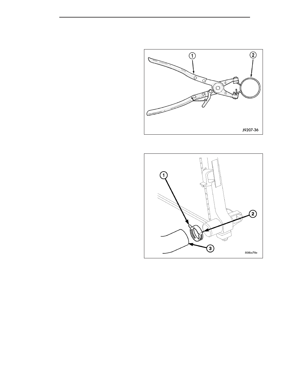
WARNING: CONSTANT TENSION HOSE CLAMPS
ARE USED ON MOST COOLING SYSTEM HOSES.
WHEN REMOVING OR INSTALLING, USE ONLY
TOOLS DESIGNED FOR SERVICING THIS TYPE OF
CLAMP, SUCH AS SPECIAL TOOL 6094. ALWAYS
WEAR SAFETY GLASSES WHEN SERVICING CON-
STANT TENSION CLAMPS.

CAUTION: A number or letter is stamped into the
tongue of constant tension clamps. If replacement
is necessary, use only an original equipment
clamp with matching number or letter.

7 - 54

ENGINE

WK

CAUTION: When removing the radiator or A/C con-
denser for any reason, note the location of all radi-
ator-to-body and radiator-to-A/C condenser rubber
air seals. These are used at the top, bottom and
sides of the radiator and A/C condenser. To pre-
vent overheating, these seals must be installed to
their original positions.

1. Disconnect the negative battery cable at battery.

2. Drain coolant from radiator (Refer to 7 - COOLING

- STANDARD PROCEDURE).

3. Remove the front grill (Refer to 23 - BODY/EXTE-

RIOR/GRILLE - REMOVAL).

4. Remove two radiator mounting bolts.

5. Disconnect both transmission cooler lines from

radiator.

6. Disconnect electrical connector for the fan control

solenoid.

7. Disconnect the power steering cooler line from cooler and filter.

8. Disconnect the radiator upper and lower hoses.

9. Disconnect the overflow hose from radiator.

10. Remove the air inlet duct at the grill.

11. The lower part of radiator is equipped with two

alignment dowel pins. They are located on the
bottom of radiator tank and fit into rubber grom-
mets. These rubber grommets are pressed into
the radiator lower crossmember.

WARNING: THE AIR CONDITIONING SYSTEM (IF
EQUIPPED) IS UNDER A CONSTANT PRESSURE
EVEN WITH THE ENGINE OFF. REFER TO REFRIG-
ERANT WARNINGS IN, HEATING AND AIR CONDI-
TIONING

BEFORE

HANDLING

ANY

AIR

CONDITIONING COMPONENT.

NOTE: The radiator and radiator cooling fan can
be removed as an assembly. It is not necessary to
remove the cooling fan before removing or install-
ing the radiator.

12. Disconnect the two high pressure fluid lines at the

hydraulic fan drive.

13. Disconnect the low pressure return hose at the

hydraulic fan drive.

14. Gently lift up and remove radiator from vehicle. Be careful not to scrape the radiator fins against any other

component. Also be careful not to disturb the air conditioning condenser (if equipped).

CLEANING

Clean radiator fins With the engine cold, apply cold water and compressed air to the back (engine side) of the
radiator to flush the radiator and/or A/C condenser of debris.

WK

ENGINE

7 - 55

INSPECTION

The radiator cooling fins should be checked for damage or deterioration. Inspect cooling fins to make sure they are
not bent or crushed, these areas result in reduced heat exchange causing the cooling system to operate at higher
temperatures. Inspect the plastic end tanks for cracks, damage or leaks.

Inspect the radiator neck for damage or distortion.

INSTALLATION

GAS ENGINES

CAUTION: Before installing the radiator or A/C condenser, be sure the radiator-to-body and radiator-to-A/C
condenser rubber air seals are properly fastened to their original positions. These are used at the top, bot-
tom and sides of the radiator and A/C condenser. To prevent overheating, these seals must be installed to
their original positions.

1. Equipped with air conditioning: Gently lower the radiator and fan shroud into the vehicle. Guide the two radiator

alignment dowels through the holes in the rubber air seals first and then through the A/C support brackets. Con-
tinue to guide the alignment dowels into the rubber grommets located in lower radiator crossmember. The holes
in the L-shaped brackets (located on bottom of A/C condenser) must be positioned between bottom of rubber air
seals and top of rubber grommets.

2. Connect the radiator upper and lower hoses and hose clamps to radiator.

CAUTION: The tangs on the hose clamps must be positioned straight down.

3. Install coolant reserve/overflow tank hose at radiator.

4. Connect both transmission cooler lines at the radiator.

5. Install both radiator mounting bolts.

6. Install air inlet duct at grill.

7. Attach electric connector for hydraulic fan control solenoid.

8. Install the grill (Refer to 23 - BODY/EXTERIOR/GRILLE - INSTALLATION).

9. Connect the two high pressure lines to the hydraulic fan drive. Tighten

1

2

in. pressure line fitting to 49 N·m (36

ft. lbs.). and the 3/8 in. pressure line fitting to 29 N·m (21.5 ft. lbs.).

10. Connect the low pressure hose to the hydraulic fan drive. Position the spring clamp.

11. Connect the power steering filter hoses to the filter. Install new hose clamps.

12. Rotate the fan blades (by hand) and check for interference at fan shroud.

13. Refill cooling system (Refer to 7 - COOLING - STANDARD PROCEDURE).

14. Refill the power steering reservoir and bleed air from system (Refer to 19 - STEERING/PUMP - STANDARD

PROCEDURE).

15. Connect battery cable at battery.

16. Start and warm engine. Check for leaks.

MOTOR-RADIATOR FAN

DIAGNOSIS AND TESTING—ELECTRIC COOLING FAN

The powertrain control module (PCM) will enter a diagnostic trouble code (DTC) in memory if it detects a problem
in the auxiliary cooling fan relay or circuit. (Refer to 25 - EMISSIONS CONTROL - DESCRIPTION).

If the electric cooling fan is inoperative, check the 15A fuse in the junction block and the 40A fuse in the Power
Distribution Center (PDC) with a 12 volt test lamp or DVOM. Refer to the inside of the PDC cover for the exact
location of the fuse. If fuses are okay, refer to ELECTRICAL SCHEMATICS for the cooling fan and relay circuit
schematic.

7 - 56

ENGINE

WK

PUMP-WATER

DESCRIPTION

DESCRIPTION - WATER PUMP - 4.7L

A centrifugal water pump circulates coolant through
the water jackets, passages, intake manifold, radiator
core, cooling system hoses and heater core. The
pump is driven from the engine crankshaft by a single
serpentine drive belt.

The water pump impeller is pressed onto the rear of a
shaft that rotates in bearings pressed into the housing.
The housing has two small holes to allow seepage to
escape. The water pump seals are lubricated by the
antifreeze in the coolant mixture. No additional lubrica-
tion is necessary.

Both heater hoses are connected to fittings on the tim-
ing chain front cover. The water pump is also mounted
directly to the timing chain cover and is equipped with
a non serviceable integral pulley.

DESCRIPTION - WATER PUMP BYPASS

The 4.7L engine uses an internal water/coolant bypass system. The design uses galleries in the timing chain cover
to circulate coolant during engine warm-up preventing the coolant from flowing through the radiator. The thermostat
uses a stub shaft located at the rear of the thermostat to control flow through the bypass gallery.

WK

ENGINE

7 - 57


Content   ..  210  211  212  213   ..