Jeep Grand Cherokee WK. Manual - part 1793


  Index      Jeep     Jeep Grand Cherokee WK - service repair manual 2005 year


Search            


Content   ..  1791  1792  1793  1794   ..


Jeep Grand Cherokee WK. Manual - part 1793


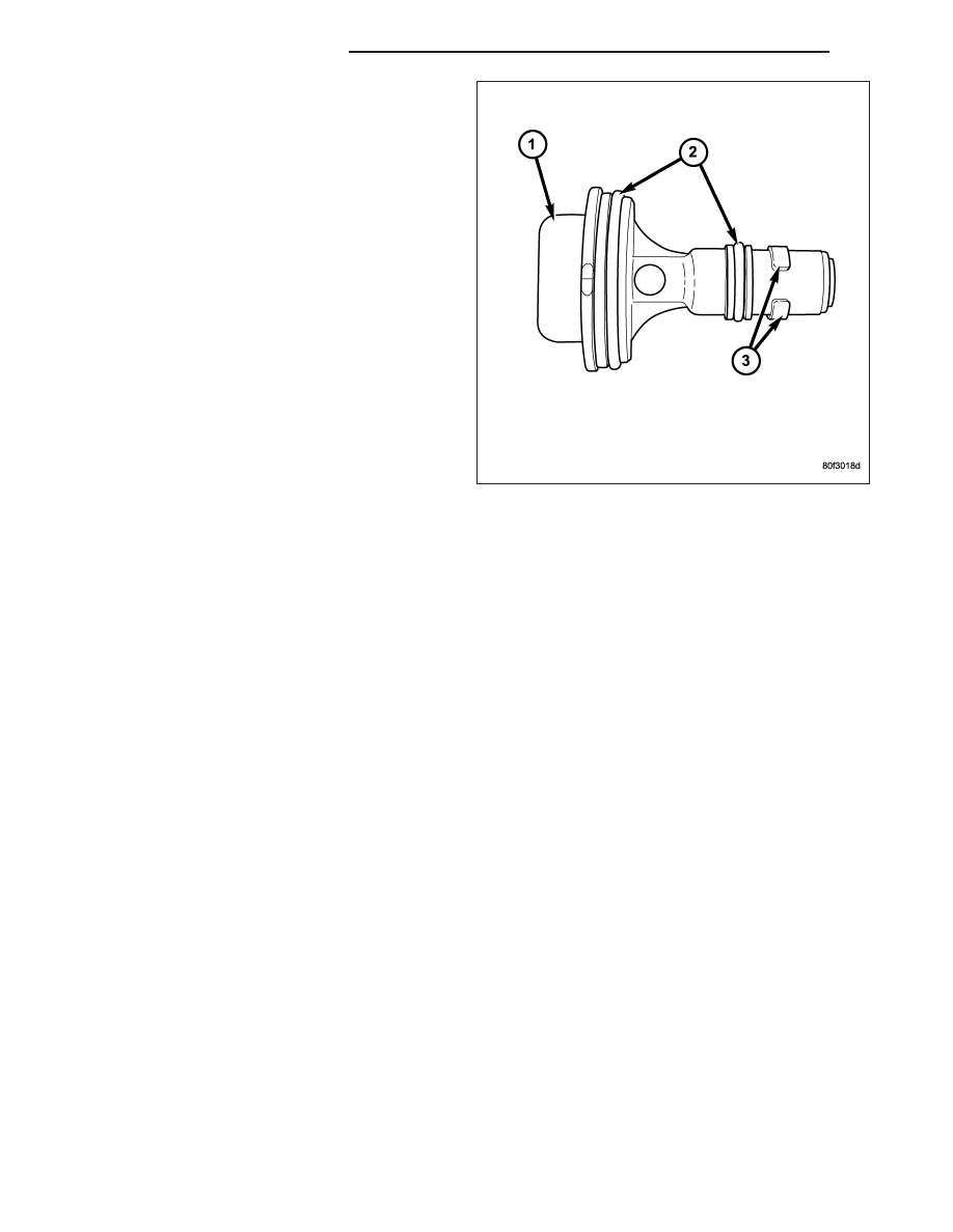
1. The PCV valve is sealed to the intake manifold

with 2 O-rings (2).

2. Remove PCV valve by rotating counter-clockwise

90 degrees until locating tabs (3) have been freed.
After tabs have cleared, pull valve straight up from
intake manifold.

3. After valve is removed, check condition of 2 valve

O-rings (2).

INSTALLATION

3.7L V6 / 4.7L V-8

The PCV valve is located on the oil filler tube. Two locating tabs are located on the side of the valve. These 2 tabs
fit into a cam lock in the oil filler tube. An o-ring seals the valve to the filler tube.

1. Return PCV valve back to oil filler tube by placing valve locating tabs into cam lock. Press PCV valve in and

rotate valve upward. A slight click will be felt when tabs have engaged cam lock. Valve should be pointed
towards rear of vehicle.

2. Connect PCV line/hose and rubber hose to PCV valve.

5.7L V-8

1. Clean out intake manifold opening.

2. Check condition of 2 o-rings on PCV valve.

3. Apply engine oil to 2 o-rings.

4. Place PCV valve into intake manifold and rotate 90 degrees clockwise for installation.

LINES-VACUUM

DESCRIPTION

A vacuum schematic for emission related items can be found on the vehicles VECI label. Refer to Vehicle Emission
Control Information (VECI) Label for label location.

25 - 24

EVAPORATIVE EMISSIONS

WK

CANISTER-VAPOR

DESCRIPTION

The EVAP canister (3) is located in the left-rear quar-
ter-panel behind the left-rear tire.

OPERATION

The EVAP canister is filled with granules of an activated carbon mixture. Fuel vapors entering the EVAP canister is
absorbed by the charcoal granules.

Fuel tank pressure vents into the EVAP canister. Fuel vapors are temporarily held in the canister until they can be
drawn into the intake manifold. The duty cycle EVAP canister purge solenoid allows the EVAP canister to be purged
at predetermined times and at certain engine operating conditions.

REMOVAL

The NVLD pump (2) is attached to the EVAP canister
(3). This assembly is located in the left-rear quarter-
panel behind the left-rear tire.

1. Raise and support vehicle.

2. Remove left-rear tire.

3. To access EVAP canister or NVLD pump, remove

plastic splash shield at rear of left-rear tire.

4. Disconnect electrical connector (4) at pump.

5. Carefully remove vapor/vacuum hoses (1) and (6)

at pump.

WK

EVAPORATIVE EMISSIONS

25 - 25

6. Remove three canister bracket-to-body nuts (1)

and (2).

7. Separate canister from mounting bracket by remov-

ing two canister-to-bracket nuts at front of canister
(4). The opposite end of canister is equipped with
two alignment pins. Remove canister from support
bracket by pulling these two pins from the two rub-
ber grommets

To Separate NVLD Pump from EVAP canister:

8. Pry outward on tab (3) and rotate pump clock-

wise about 70 degrees for removal.

25 - 26

EVAPORATIVE EMISSIONS

WK

9. Remove NVLD pump o-ring (2) from EVAP canister

(1).

INSTALLATION

To Install NVLD Pump to EVAP canister:

1. Install new NVLD pump o-ring (2) to EVAP canister

(1).

WK

EVAPORATIVE EMISSIONS

25 - 27


Content   ..  1791  1792  1793  1794   ..