Jeep Grand Cherokee WK. Manual - part 1791


  Index      Jeep     Jeep Grand Cherokee WK - service repair manual 2005 year


Search            


Content   ..  1789  1790  1791  1792   ..


Jeep Grand Cherokee WK. Manual - part 1791


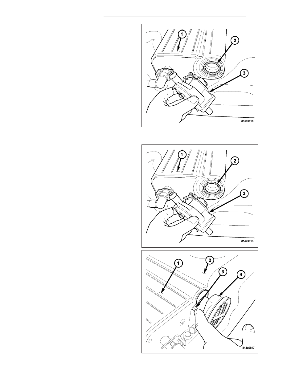
7. Remove NVLD pump o-ring (2) from EVAP canister

(1).

INSTALLATION

1. Install new NVLD pump o-ring (2) to EVAP canister

(1).

2. Position NVLD pump (4) into EVAP canister (1).

3. Rotate pump (4) until tab (3) aligns with notch in

EVAP canister (1).

25 - 16

EVAPORATIVE EMISSIONS

WK

4. Carefully install vapor/vacuum lines (1) and (6) to

NVLD pump and EVAP canister. The vapor/vac-
uum lines and hoses must be firmly connected.
Check the vapor/vacuum lines at the NVLD
pump, filter and EVAP canister purge solenoid
for damage or leaks. If a leak is present, a Diag-
nostic Trouble Code (DTC) may be set.

5. Connect electrical connector (4) to pump.

6. Install plastic splash shield at rear of left-rear tire.

7. Install left-rear tire.

VALVE-PCV

DESCRIPTION

3.7L V-6 / 4.7L V-8

The 3.7L V-6 and 4.7L V-8 engines are equipped with
a closed crankcase ventilation system. The Positive
Crankcase Ventilation (PCV) valve (6) is mounted to
the oil filler housing (4).

The PCV valve is sealed to the oil filler housing with
an o-ring (1).

WK

EVAPORATIVE EMISSIONS

25 - 17

Two interconnected breathers (1) threaded into the
rear of each cylinder head are used with the system.

The system also includes the air cleaner housing and
various tubes and hoses to connect the system
components.

5.7L V-8

The 5.7L V-8 engine is equipped with a closed crank-
case ventilation system and a Positive Crankcase
Ventilation (PCV) valve.

A PCV valve (4) mounted into the top of the intake
manifold (1), located to the right / rear of the throttle
body (2) is used.

25 - 18

EVAPORATIVE EMISSIONS

WK

The PCV valve (1) is sealed to the intake manifold
with two o-rings (2).

The system also consists of passages in the intake
manifold, and various tubes and hoses to connect the
system components.

OPERATION

A typical enclosed crankcase ventilation system is
shown in the graphic.

The PCV system operates by engine intake manifold
vacuum. Filtered air is routed into the crankcase
through the air cleaner hose. The metered air, along
with crankcase vapors, are drawn through the PCV
valve (4) and into a passage in the intake manifold.
The PCV system manages crankcase pressure and
meters blow by gases to the intake system, reducing
engine sludge formation.

The PCV valve contains a spring loaded plunger. This
plunger meters the amount of crankcase vapors
routed into the combustion chamber based on intake
manifold vacuum.

WK

EVAPORATIVE EMISSIONS

25 - 19


Content   ..  1789  1790  1791  1792   ..