Jeep Grand Cherokee WK. Manual - part 1406


  Index      Jeep     Jeep Grand Cherokee WK - service repair manual 2005 year


Search            


Content   ..  1404  1405  1406  1407   ..


Jeep Grand Cherokee WK. Manual - part 1406


TURBINE

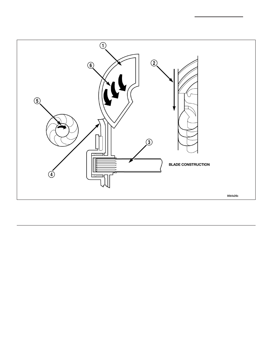
The turbine is the output, or driven, member of the converter. The turbine is mounted within the housing opposite
the impeller, but is not attached to the housing. The input shaft is inserted through the center of the impeller and
splined into the turbine. The design of the turbine is similar to the impeller, except the blades of the turbine are
curved in the opposite direction.

Turbine

1 - TURBINE VANE

4 - PORTION OF TORQUE CONVERTER COVER

2 - ENGINE ROTATION

5 - ENGINE ROTATION

3 - INPUT SHAFT

6 - OIL FLOW WITHIN TURBINE SECTION

21 - 434

AUTOMATIC TRANSMISSION - 545RFE - SERVICE INFORMATION

WK

STATOR

The stator assembly is mounted on a stationary shaft
which is an integral part of the oil pump. The stator (1)
is located between the impeller (2) and the turbine (4)
within the torque converter case.

The stator contains an over-running clutch (1-4), which
allows the stator to rotate only in a clockwise direction.
When the stator is locked against the over-running
clutch, the torque multiplication feature of the torque
converter is operational.

WK

AUTOMATIC TRANSMISSION - 545RFE - SERVICE INFORMATION

21 - 435

TORQUE CONVERTER CLUTCH (TCC)

The TCC was installed to improve the efficiency of the
torque converter that is lost to the slippage of the fluid
coupling. Although the fluid coupling provides smooth,
shock-free power transfer, it is natural for all fluid cou-
plings to slip. If the impeller (3) and turbine (5) were
mechanically locked together, a zero slippage condi-
tion could be obtained. A hydraulic piston (6) with fric-
tion material (7) was added to the turbine assembly
(5) to provide this mechanical lock-up.

In order to reduce heat build-up in the transmission
and buffer the powertrain against torsional vibrations,
the TCM can duty cycle the L/R-CC Solenoid to
achieve a smooth application of the torque converter
clutch. This function, referred to as Electronically Mod-
ulated Converter Clutch (EMCC) can occur at various
times depending on the following variables:

Shift lever position

Current gear range

Transmission fluid temperature

Engine coolant temperature

Input speed

Throttle angle

Engine speed

OPERATION

The converter impeller (driving member), which is integral to the converter housing and bolted to the engine drive
plate, rotates at engine speed. The converter turbine (driven member), which reacts from fluid pressure generated
by the impeller, rotates and turns the transmission input shaft.

21 - 436

AUTOMATIC TRANSMISSION - 545RFE - SERVICE INFORMATION

WK

TURBINE

As the fluid that was put into motion by the impeller blades strikes the blades of the turbine, some of the energy and
rotational force is transferred into the turbine and the input shaft. This causes both of them (turbine and input shaft)
to rotate in a clockwise direction following the impeller. As the fluid is leaving the trailing edges of the turbine’s
blades it continues in a “hindering” direction back toward the impeller. If the fluid is not redirected before it strikes
the impeller, it will strike the impeller in such a direction that it would tend to slow it down.

STATOR

Torque multiplication is achieved by locking the stator’s over-running clutch to its shaft. Under stall conditions (the
turbine is stationary), the oil leaving the turbine blades strikes the face of the stator blades and tries to rotate them
in a counterclockwise direction. When this happens the over-running clutch of the stator locks and holds the stator
from rotating. With the stator locked, the oil strikes the stator blades and is redirected into a “helping” direction
before it enters the impeller. This circulation of oil from impeller to turbine, turbine to stator, and stator to impeller,
can produce a maximum torque multiplication of about 2.4:1. As the turbine begins to match the speed of the impel-
ler, the fluid that was hitting the stator in such as way as to cause it to lock-up is no longer doing so. In this con-
dition of operation, the stator begins to free wheel and the converter acts as a fluid coupling.

Torque Converter Fluid Operation - Typical

1 - APPLY PRESSURE

3 - RELEASE PRESSURE

2 - THE PISTON MOVES SLIGHTLY FORWARD

4 - THE PISTON MOVES SLIGHTLY REARWARD

WK

AUTOMATIC TRANSMISSION - 545RFE - SERVICE INFORMATION

21 - 437


Content   ..  1404  1405  1406  1407   ..