Content .. 1403 1404 1405 1406 ..
Jeep Grand Cherokee WK. Manual - part 1405
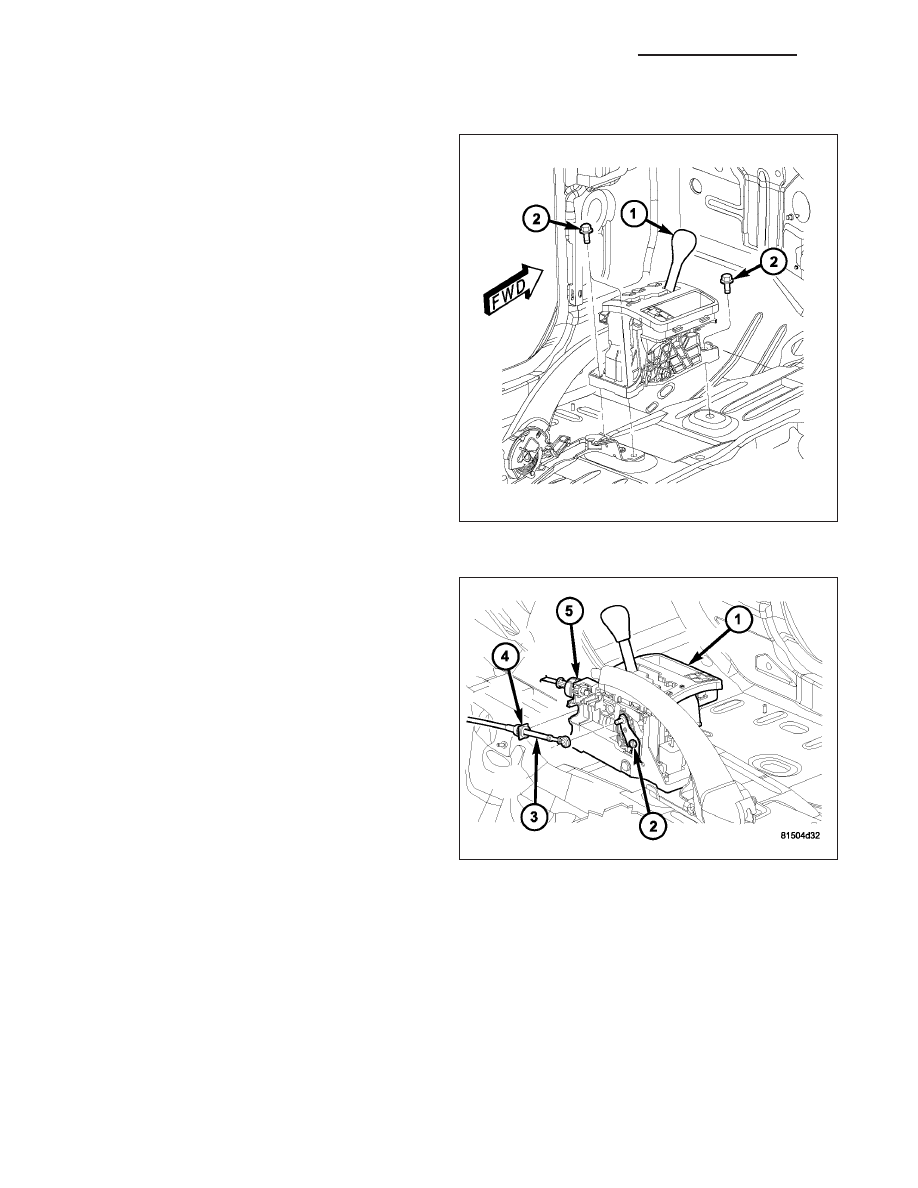
INSTALLATION
1. Install shifter assembly (1) in position on the floor
pan.
2. Install the bolts (2) to hold the shifter assembly (1)
onto the floor pan. Tighten bolts to 12 N·m (105
in.lbs.).
3. Place the floor shifter lever in PARK position.
4. Loosen the adjustment nut (2) on the shifter
assembly (1).
5. Install the gearshift cable (3) to the shift lever pin.
6. Install the park lock cable (5) to the shift mecha-
nism cam and the notch in the shifter assembly.
7. Verify that the key is in the LOCK position and
remains there until the cable is fully adjusted.
8. Verify that the park lock cable adjustment tab is
pulled upward to the unlocked position.
21 - 430
AUTOMATIC TRANSMISSION - 545RFE - SERVICE INFORMATION
WK