Jeep Grand Cherokee WK. Manual - part 1171


  Index      Jeep     Jeep Grand Cherokee WK - service repair manual 2005 year


Search            


Content   ..  1169  1170  1171  1172   ..


Jeep Grand Cherokee WK. Manual - part 1171


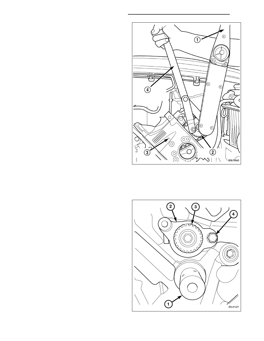
6. Position the camshaft drive gear onto the camshaft,

remove oil from bolt then install the retaining bolt.
Using Special Tools, Spanner Wrench 6958 with
Adapter Pins 8346 (4) and a suitable torque
wrench (1), tighten retaining bolt to 122 N·m (90 ft.
Lbs.).

7. Remove Special Tool 8379.

8. Rotate the crankshaft two full revolutions, then ver-

ify that the camshaft drive gear V6 marks are in
fact aligned.

9. Install the cylinder head covers (Refer to 9 -

ENGINE/CYLINDER

HEAD/CYLINDER

HEAD

COVER(S) - INSTALLATION).

SHAFT-BALANCE

REMOVAL

1. Remove the primary and secondary timing chains.

(Refer to 9 - ENGINE/VALVE TIMING/TIMING
BELT/CHAIN AND SPROCKETS - REMOVAL).

NOTE: The balance shaft and gear are serviced as
an assembly. Do not attempt to remove the gear
from the balance shaft.Remove the retaining bolt
(4) from the counterbalance shaft thrust plate (2).

9 - 1280

ENGINE - 3.7L SERVICE INFORMATION

WK

2. Using Special Tool 8641 Counterbalance shaft

remover/installer tool (1), remove the counterbal-
ance shaft from the engine.

INSTALLATION

NOTE: The balance shaft and gear are serviced as an assembly. Do not attempt to remove the gear from the
balance shaft.

1. Coat counterbalance shaft bearing journals with clean engine oil.

NOTE: The balance shaft is heavy, and care should be used when installing shaft, so bearings are not dam-
aged.

2. Using Special Tool 8641 Counterbalance shaft remover/installer tool, carefully install counterbalance shaft into

engine.

3. Install Counterbalance shaft thrust plate retaining bolt finger tight.Do not tighten bolt at this time.

4. Position the right side of the thrust plate with the right chain guide bolt, install bolt finger tight.

5. Torque the thrust plate retaining bolt to 28 N·m (250 in. lbs.).

6. Remove the chain guide bolt so that guide can be installed.

IDLER SHAFT

REMOVAL

1. Remove the primary and secondary timing chains and sprockets. Refer to procedure in this section.

NOTE: To remove the idler shaft, it is necessary to tap threads into the shaft, to install the removal tool.

2. Using a 12 mm X 1.75 tap, cut threads in the idler shaft center bore.

3. Cover the radiator core with a suitable cover.

CAUTION: Use care when removing the idler shaft, Do not strike the radiator cooling fins with the slide
hammer.

4. Using Special Tool 8517 Slide Hammer, remove the idler shaft.

WK

ENGINE - 3.7L SERVICE INFORMATION

9 - 1281

INSTALLATION

1. Thoroughly clean the idler shaft bore.

2. Position the idler shaft in the bore.

NOTE: The two lubrication holes in the idler shaft do not require any special alignment.

NOTE: Before using the retaining bolt to install the idler shaft, coat the threads and the pilot on the idler
shaft, with clean engine oil.

3. Using the primary idler sprocket retaining bolt and washer, carefully draw the idler shaft into the bore until fully

seated.

4. Coat the idler shaft with clean engine oil.

5. Install the timing chains and sprockets. Refer to procedure in this section.

COVER - TIMING

REMOVAL

1. Disconnect the battery negative cable.

2. Drain cooling system (Refer to 7 - COOLING -

STANDARD PROCEDURE).

3. Remove electric cooling fan and fan shroud assem-

bly.

4. Remove radiator fan (Refer to 7 - COOLING/EN-

GINE/RADIATOR FAN - REMOVAL).

5. Disconnect both heater hoses at timing cover.

6. Disconnect lower radiator hose at engine.

7. Remove accessory drive belt tensioner assembly

(1).

8. Remove crankshaft damper (Refer to 9 - ENGINE/

ENGINE

BLOCK/VIBRATION

DAMPER

-

REMOVAL).

9. Remove the generator (Refer to 8 - ELECTRICAL/

CHARGING/GENERATOR - REMOVAL).

10. Remove A/C compressor (Refer to 24 - HEATING

& AIR

CONDITIONING/PLUMBING/A/C

COM-

PRESSOR - REMOVAL).

CAUTION: The 3.7L engine uses an anerobic
sealer instead of a gasket to seal the front cover to the engine block, from the factory. For service, Mopar

T

Grey Engine RTV sealant must be substituted.

NOTE: It is not necessary to remove the water pump for timing cover removal.

9 - 1282

ENGINE - 3.7L SERVICE INFORMATION

WK

11. Remove the bolts holding the timing cover to

engine block.

12. Remove the timing cover.

INSTALLATION

CAUTION: Do not use oil based liquids to clean
timing cover or block surfaces. Use only rubbing
alcohol, along with plastic or wooden scrapers.
Use no wire brushes or abrasive wheels or metal
scrapers, or damage to surfaces could result.

1. Clean timing chain cover and block surface using

rubbing alcohol.

CAUTION: The 3.7L uses a special anerobic sealer
instead of a gasket to seal the timing cover to the
engine block, from the factory. For service repairs,
Mopar

T

Engine RTV must be used as a substitute.

2. Inspect the water passage o-rings (2) for any dam-

age, and replace as necessary.

3. Apply Mopar

T

Engine RTV sealer to front cover as

shown (3) using a 3 to 4mm thick bead.

WK

ENGINE - 3.7L SERVICE INFORMATION

9 - 1283


Content   ..  1169  1170  1171  1172   ..