Content .. 1167 1168 1169 1170 ..
Jeep Grand Cherokee WK. Manual - part 1169
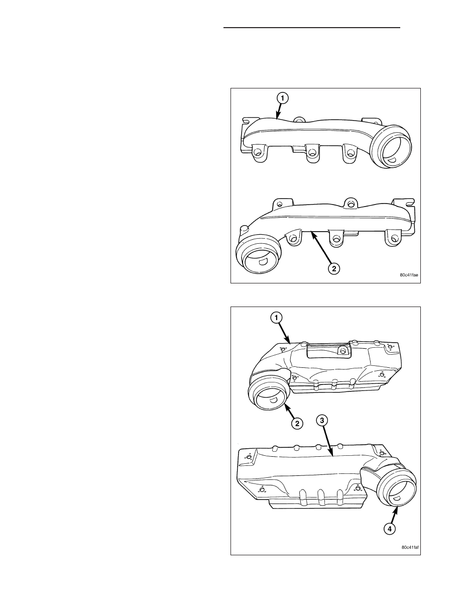
MANIFOLD-EXHAUST
DESCRIPTION
The exhaust manifolds( 1 and 2) are log style with a
patented flow enhancing design to maximize perfor-
mance. The exhaust manifolds are made of high sili-
con molybdenum cast iron. A perforated core graphite
exhaust manifold gasket is used to improve sealing to
the cylinder head.
The exhaust manifolds are covered by a three layer
laminated heat shield ( 1 and 3) for thermal protection
and noise reduction. The heat shields(1 and 3) are
fastened with a torque prevailing nut that is backed off
slightly to allow for the thermal expansion of the
exhaust manifold.
9 - 1272
ENGINE - 3.7L SERVICE INFORMATION
WK