Content .. 1038 1039 1040 1041 ..
Jeep Grand Cherokee WK. Manual - part 1040
P0703-BRAKE SWITCH 2 PERFORMANCE (CONTINUED)
2.
(F942) FUSED IGNITION SWITCH CIRCUIT
Turn the ignition off.
Disconnect the Stop Lamp Switch harness connector.
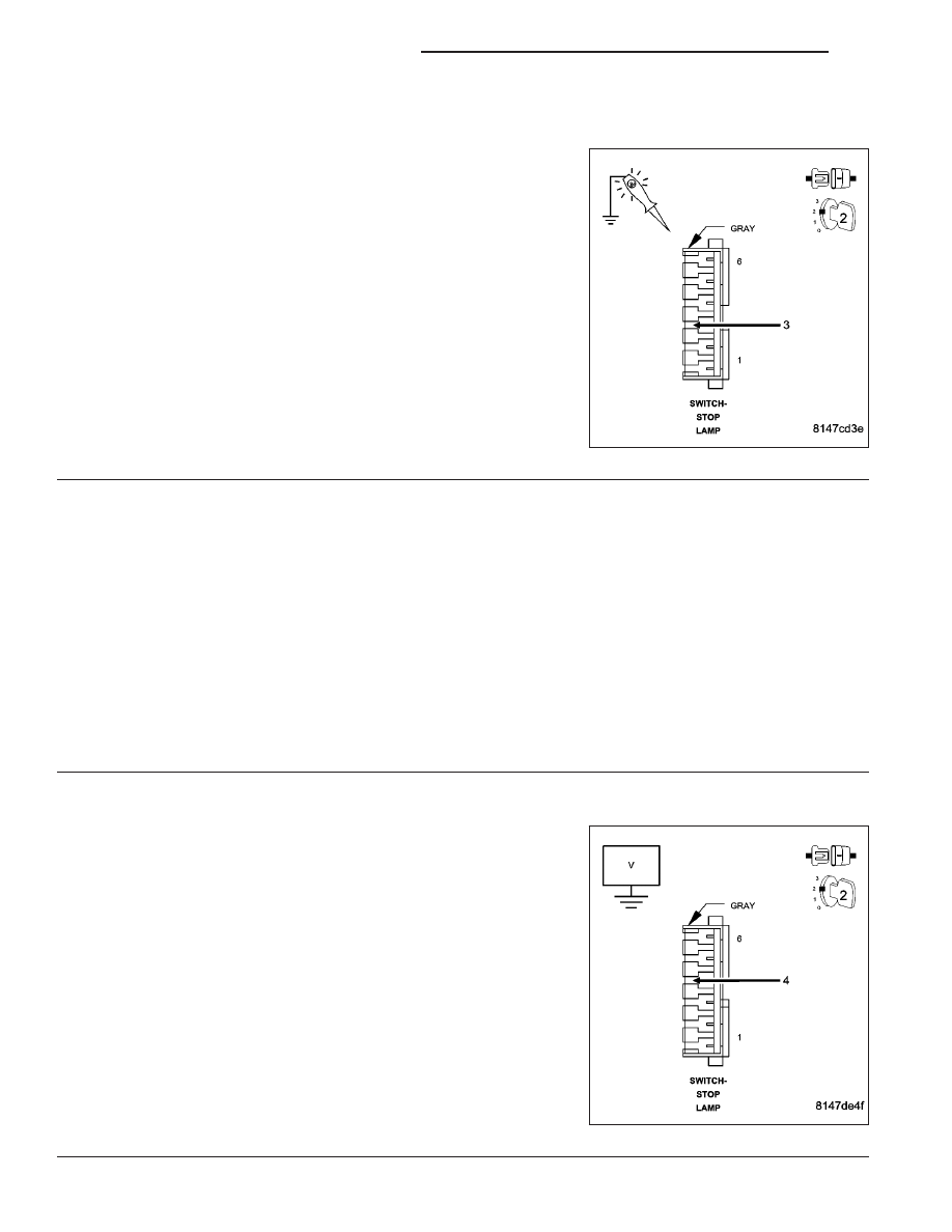
Using a 12-volt test light connected to ground, probe the (F942) Fused
Ignition Switch Output circuit in the Stop Lamp Switch harness con-
nector.
Does the test light illuminate brightly?
Yes
>> Go To 3
No
>> Repair the open or short to ground in the (F942) Fused
Ignition Switch Output circuit. Inspect the related fuse and
repair as necessary.
Perform the POWERTRAIN VERIFICATION TEST. (Refer
to 9 - ENGINE - STANDARD PROCEDURE)
3.
STOP LAMP SWITCH
Turn the ignition off.
Measure the resistance between the (F942) Fused Ignition Switch Output circuit terminal and the (B16) Brake
Switch No.2 Signal circuit terminal in the Stop Lamp Switch.
Measure the resistance between the (Z904) Ground circuit terminal and the (B15) Brake Switch No.1 Signal terminal
in the Stop Lamp Switch.
Apply and release the Stop Lamp Switch while monitoring the ohmmeter.
Does the resistance change from below 5.0 ohms to open circuit for each circuit check?
Yes
>> Go To 4
No
>> Replace the Stop Lamp Switch.
Perform the POWERTRAIN VERIFICATION TEST. (Refer to 9 - ENGINE - STANDARD PROCEDURE)
4.
(B16) BRAKE SWITCH NO.2 SIGNAL CIRCUIT SHORTED TO BATTERY VOLTAGE
Disconnect the C3 PCM harness connector.
Measure the voltage on the (B16) Brake Switch No.2 Signal circuit in
the Stop Lamp Switch harness connector.
Ignition on, engine not running.
Is the voltage above 0 volts?
Yes
>> Repair the short to battery voltage in the (B16) Brake
Switch No.2 Signal circuit.
Perform the POWERTRAIN VERIFICATION TEST. (Refer
to 9 - ENGINE - STANDARD PROCEDURE)
No
>> Go To 5
9 - 756
ENGINE ELECTRICAL DIAGNOSTICS
WK