Jeep Grand Cherokee WJ. Manual - part 938


  Index      Jeep     Jeep Grand Cherokee WJ - service repair manual 2001 year


Search            


Content   ..  936  937  938  939   ..


Jeep Grand Cherokee WJ. Manual - part 938


TRANSFER CASE - NV247

TABLE OF CONTENTS

page

page

TRANSFER CASE - NV247

REMOVAL . . . . . . . . . . . . . . . . . . . . . . . . . . . . . 259
DISASSEMBLY . . . . . . . . . . . . . . . . . . . . . . . . . . 260
INSPECTION . . . . . . . . . . . . . . . . . . . . . . . . . . . 267
ASSEMBLY . . . . . . . . . . . . . . . . . . . . . . . . . . . . 268
INSTALLATION . . . . . . . . . . . . . . . . . . . . . . . . . . 277

SPECIFICATIONS. . . . . . . . . . . . . . . . . . . . . . . . 278
SPECIAL TOOLS . . . . . . . . . . . . . . . . . . . . . . . . 279

FLUID

STANDARD PROCEDURE . . . . . . . . . . . . . . . . . 280

FLUID DRAIN/REFILL . . . . . . . . . . . . . . . . . . . 280

TRANSFER CASE - NV247

REMOVAL

(1) Open the hood and disconnect the negative bat-

tery cable.

(2) Remove the (2) upper fan shroud retaining

bolts.

(3) Raise the vehicle on a hoist.
(4) Remove the (2) lower fan shroud retaining

bolts.

CAUTION: Mark the position of the driveshaft in
relation to its companion flange prior to disassem-
bly. Driveshaft must be reinstalled in the same posi-
tion it was in prior to disassembly.

(5) Remove the front driveshaft retaining bolts

(Fig. 1) and remove the driveshaft from the transfer
case companion flange. Support the driveshaft with
mechanics wire.

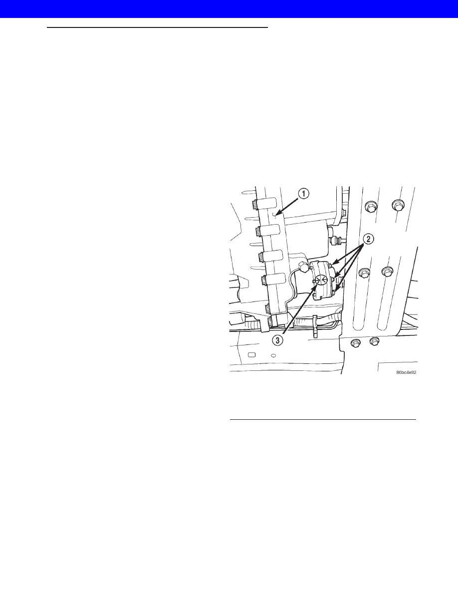
(6) Remove the rear driveshaft retaining bolts and

remove the driveshaft from the transfer case compan-
ion flange. Support the driveshaft with mechanics
wire (Fig. 2).

(7) Disconnect the transfer case shift cable from

the shifter arm (Fig. 3).

Fig. 1 Front Driveshaft Retaining Bolts

1 - TRANSFER CASE
2 - FRONT DRIVESHAFT RETAINING BOLTS
3 - REFERENCE MARK

WG

TRANSFER CASE - NV247

21s - 259

2001 JEEP GRAND CHEROKEE

(8) Disconnect the vent tube from the transfer case

(Fig. 3).

(9) Remove the transmission oil pan and drain the

transmission fluid. Reinstall the transmission oil
pan.

(10) Position a jack under the transmission sup-

port crossmember and support the transmission and
transfer case assembly.

(11) Remove the (8) transmission support cross-

member retaining bolts (Fig. 4).

(12) Position a transmission jack under the trans-

fer case.

(13) Lower the transmission assembly enough to

gain access and remove the transfer case to trans-
mission retaining nuts.

(14) Remove the transfer case from the vehicle.

DISASSEMBLY

Position transfer case on shallow drain pan.

Remove drain plug and drain lubricant remaining in
case.

REAR CASE AND OIL PUMP

(1) Remove the bolts (Fig. 5) holding the transfer

case damper to the transfer case.

Fig. 2 Rear Driveshaft - Supported

1 - REAR DRIVESHAFT

Fig. 3 Transfer Case Position and Orientation

1 - TRANSFER CASE RETAINING NUTS
2 - TRANSFER CASE SHIFTER CABLE
3 - TRANSFER CASE VENT HOSE
4 - FLAT BLADED TOOL
5 - TRANSFER CASE
6 - TRANSMISSION ELECTRICAL CONNECTOR

Fig. 4 Transmission Support Crossmember Position

and Orientation

1 - TRANSFER CASE
2 - TRANSMISSION MOUNT RETAINING BOLTS (2 OF 4)
3 - EXHAUST SYSTEM SUPPORT BRACKET RETAINING BOLTS
4 - CROSSMEMBER RETAINING BOLTS
5 - TRANSMISSION
6 - CROSSMEMBER RETAINING BOLTS

21s - 260

TRANSFER CASE - NV247

WG

TRANSFER CASE - NV247 (Continued)

2001 JEEP GRAND CHEROKEE

(2) Remove the damper (Fig. 6) from the transfer

case.

(3) Install two bolts (Fig. 7) partially into the rear

propellor shaft companion flange, 180° from each
other.

(4) Install the rectangular end of the Flange

Holder C-3281 over the bolts to hold the companion
flange stationary and remove the nut holding the
companion flange to the rear output shaft.

(5) Use Remover C-452 (Fig. 8) to remove the rear

companion flange.

(6) Support transfer case so rear case is facing

upward.

Fig. 5 Remove Damper Bolts

1 - DAMPER
2 - TRANSFER CASE
3 - BOLTS

Fig. 6 Remove Damper

1 - DAMPER
2 - TRANSFER CASE

Fig. 7 Hold Companion Flange

1 - HOLDER C-3281
2 - BOLTS
3 - COMPANION FLANGE

Fig. 8 Remove Companion Flange

1 - TRANSFER CASE
2 - COMPANION FLANGE
3 - REMOVER C-452

WG

TRANSFER CASE - NV247

21s - 261

TRANSFER CASE - NV247 (Continued)

2001 JEEP GRAND CHEROKEE

(7) Remove bolts holding front case to rear case.

The case alignment bolt require flat washers (Fig. 9).

(8) Loosen rear case with flat blade screwdriver to

break sealer bead. Insert screwdriver blade only into
notches provided at each end of case (Fig. 10).

(9) Remove rear case.

(10) Remove the screws holding the transfer case

chain snubber (Fig. 11) to the rear transfer case half.

(11) Remove the oil pump retaining snap-ring (Fig.

12).

(12) Disengage oil pickup tube from oil pump (Fig.

13).

(13) Remove oil pump assembly (Fig. 14).
(14) Remove pick-up tube o-ring from oil pump

(Fig. 15), if necessary. Do not disassemble the oil
pump, it is not serviceable.

Fig. 9 Rear Case Alignment Bolt Locations

1 - ALIGNMENT BOLT AND WASHER (AT EACH END OF CASE)

Fig. 10 Rear Case Removal

1 - REAR TRANSFER CASE HALF
2 - SCREWDRIVER SLOTS

Fig. 11 Remove Transfer Case Chain Snubber

1 - TRANSFER CASE CHAIN SNUBBER
2 - REAR CASE HALF

Fig. 12 Remove Oil Pump Snap-ring

1 - OIL PUMP SNAP-RING
2 - OIL PUMP

21s - 262

TRANSFER CASE - NV247

WG

TRANSFER CASE - NV247 (Continued)

2001 JEEP GRAND CHEROKEE


Content   ..  936  937  938  939   ..