Jeep Grand Cherokee WJ. Manual - part 939


  Index      Jeep     Jeep Grand Cherokee WJ - service repair manual 2001 year


Search            


Content   ..  937  938  939  940   ..


Jeep Grand Cherokee WJ. Manual - part 939


COMPANION FLANGE AND RANGE LEVER

(1) Remove front companion flange nut as follows:

(a) Move range lever to 4L position.
(b) Remove nut with socket and impact wrench.

(2) Remove companion flange. If flange is difficult

to remove by hand, remove it with bearing splitter, or
with standard two jaw puller. Be sure puller tool is
positioned on flange and not on slinger as slinger will
be damaged.

(3) Remove seal washer from front output shaft.

Discard washer as it should not be reused.

(4) Remove nut and washer that attach range

lever to sector shaft. Then move sector to neutral
position and remove range lever from shaft.

NOTE: Note position of range lever so it can be re-
installed correctly.

PROGRESSIVE COUPLING

(1) Remove progressive coupling locating snap-ring

(Fig. 16) and progressive coupling thrust washer
(Fig. 17) from the mainshaft.

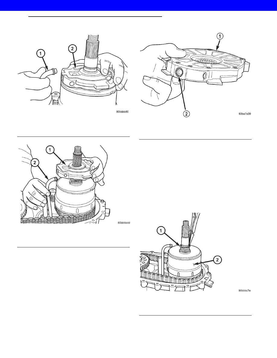
Fig. 13 Disengage Oil Pump Tube From Oil Pump

1 - OIL PUMP PICKUP TUBE
2 - OIL PUMP

Fig. 14 Remove Oil Pump

1 - OIL PUMP
2 - OIL PUMP PICKUP TUBE

Fig. 15 Pick-up Tube O-ring Location

1 - OIL PUMP
2 - O-RING

Fig. 16 Remove Progressive Coupler Snap-ring

1 - PROGRESSIVE COUPLING SNAP-RING
2 - PROGRESSIVE COUPLING

WG

TRANSFER CASE - NV247

21s - 263

TRANSFER CASE - NV247 (Continued)

2001 JEEP GRAND CHEROKEE

(2) Remove progressive coupling from mainshaft

(Fig. 18).

FRONT OUTPUT SHAFT AND DRIVE CHAIN

(1) Remove rear output shaft drive gear snap-ring

(Fig. 19).

(2) Disengage

drive

gear

(Fig.

20).

Pry

gear

upward and off mainshaft as shown.

(3) Remove front output shaft, drive chain and

drive gear as assembly (Fig. 20).

Fig. 17 Remove Progressive Coupler Thrust Washer

1 - PROGRESSIVE COUPLING THRUST WASHER
2 - PROGRESSIVE COUPLING

Fig. 18 Remove Progressive Coupler

1 - PROGRESSIVE COUPLING
2 - MAINSHAFT

Fig. 19 Remove Output Shaft Drive Gear Snap-ring

1 - REAR OUTPUT SHAFT DRIVE GEAR SNAP-RING
2 - REAR OUTPUT SHAFT

Fig. 20 Front Output Shaft, Drive Gear And Chain

Removal

1 - REAR HOUSING
2 - OUTPUT SHAFT AND SPROCKET
3 - MAINSHAFT SPROCKET
4 - SNAP-RING
5 - DRIVE CHAIN

21s - 264

TRANSFER CASE - NV247

WG

TRANSFER CASE - NV247 (Continued)

2001 JEEP GRAND CHEROKEE

(4) Remove front output shaft drive gear snap-

ring. (Fig. 21)

(5) Remove output shaft drive gear from front out-

put shaft. (Fig. 22)

(6) Remove the oil pump pickup tube from the

front case half. (Fig. 23)

SHIFT FORKS AND MAINSHAFT

(1) Remove detent plug, O-ring, detent spring and

detent plunger (Fig. 24).

(2) Remove shift rail from shift fork and transfer

case housing.

(3) Rotate range shift fork until it disengages from

shift sector.

(4) Remove mainshaft and shift fork from input

gear pilot bearing.

NOTE: Loose needle bearings are used to support
the drive sprocket hub on the mainshaft. Do not lift
mainshaft by drive sprocket hub or needle bearings
will become dislodged.

(5) Wrap rag around mainshaft underneath drive

sprocket hub and remove drive sprocket hub from
mainshaft. Be sure to retrieve all the drive sprocket
hub needle bearings.

(6) Remove snap ring holding clutch sleeve onto

mainshaft.

Fig. 21 Remove Front Output Shaft Drive Gear

Snap-ring

1 - FRONT OUTPUT SHAFT DRIVE GEAR SNAP-RING
2 - FRONT OUTPUT SHAFT

Fig. 22 Remove Front Output Shaft Drive Gear

1 - FRONT OUTPUT SHAFT DRIVE GEAR
2 - FRONT OUTPUT SHAFT

Fig. 23 Remove Oil Pump Pickup Tube

1 - OIL PUMP PICKUP TUBE
2 - FRONT CASE HALF

Fig. 24 Detent Plug, Spring And Plunger Removal

1 - DETENT PLUG
2 - DETENT SPRING
3 - DETENT PLUNGER
4 - PLUG O-RING

WG

TRANSFER CASE - NV247

21s - 265

TRANSFER CASE - NV247 (Continued)

2001 JEEP GRAND CHEROKEE

(7) Remove range clutch sleeve, blockout spring,

locking clutch, and locking clutch spring from main-
shaft (Fig. 25).

(8) Remove shift sector. Rotate and tilt sector as

needed to remove it.

(9) Remove shift sector bushing and O-ring (Fig.

26).

INPUT GEAR/LOW RANGE ASSEMBLY

(1) Turn front case on side so that the input shaft

is facing upward.

(2) Remove the input shaft seal with a suitable

screw mounted in a slide hammer.

(3) Remove snap-ring that retains input gear shaft

in front bearing.

(4) Remove input and low range gear assembly

(Fig. 27).

INPUT AND LOW RANGE GEAR

(1) Remove snap-ring that retains input gear in

low range gear (Fig. 28).

(2) Remove retainer (Fig. 29).
(3) Remove front tabbed thrust washer (Fig. 30).
(4) Remove input gear (Fig. 31).
(5) Remove rear tabbed thrust washer from low

range gear (Fig. 32).

Fig. 25 Range Clutch Sleeve, Blockout Spring,

Locking Clutch and Spring

1 - LOCKING CLUTCH SPRING
2 - BLOCKOUT SPRING
3 - SNAP-RING
4 - RANGE CLUTCH SLEEVE
5 - LOCKING CLUTCH
6 - DRIVE SPROCKET HUB

Fig. 26 Sector Bushing And O-Ring Removal

1 - SHIFT SECTOR BUSHING
2 - O-RING

Fig. 27 Input And Low Range Gear Assembly

Removal

1 - INPUT AND LOW RANGE GEAR ASSEMBLY

Fig. 28 Input Gear Snap-Ring Removal

1 - INPUT GEAR SNAP-RING

21s - 266

TRANSFER CASE - NV247

WG

TRANSFER CASE - NV247 (Continued)

2001 JEEP GRAND CHEROKEE


Content   ..  937  938  939  940   ..