Jeep Grand Cherokee WJ. Manual - part 882


  Index      Jeep     Jeep Grand Cherokee WJ - service repair manual 2001 year


Search            


Content   ..  880  881  882  883   ..


Jeep Grand Cherokee WJ. Manual - part 882


GEARSHIFT CABLE

DIAGNOSIS AND TESTING - GEARSHIFT
CABLE

(1) The floor shifter lever and gate positions

should be in alignment with all transmission PARK,
NEUTRAL, and gear detent positions.

(2) Engine starts must be possible with floor shift

lever in PARK or NEUTRAL gate positions only.
Engine starts must not be possible in any other gear
position.

(3) With floor shift lever handle push-button not

depressed and lever in:

(a) PARK position - Apply forward force on cen-

ter of handle and remove pressure. Engine starts
must be possible.

(b) PARK position - Apply rearward force on cen-

ter of handle and remove pressure. Engine starts
must be possible.

(c) NEUTRAL position - Normal position. Engine

starts must be possible.

(d) NEUTRAL position - Engine running and

brakes applied, apply forward force on center of
shift handle. Transmission shall not be able to shift
from NEUTRAL to REVERSE.

REMOVAL

(1) Shift transmission into PARK.
(2) Raise vehicle.
(3) Remove the shift cable eyelet from the trans-

mission manual shift lever (Fig. 26).

(4) Remove shift cable from the cable support

bracket.

(5) Lower vehicle.

(6) Remove necessary console parts for access to

shift lever assembly and shift cable. (Refer to 23 -
BODY/INTERIOR/FLOOR CONSOLE - REMOVAL)

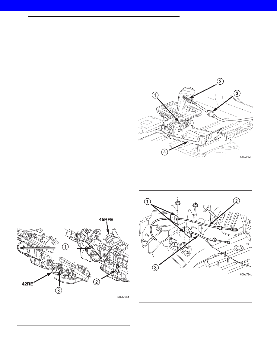
(7) Disconnect cable at shift lever and shifter

assembly bracket (Fig. 27).

(8) Remove the nuts holding the shift cable seal

plate to the floor pan (Fig. 28).

(9) Pull cable through floor panel opening.

(10) Remove shift cable from vehicle.

INSTALLATION

(1) Route cable through hole in floor pan.
(2) Install seal plate to studs in floor pan.

Fig. 26 Remove Shift Cable From Transmission

1 - SHIFT CABLE
2 - MANUAL LEVER
3 - MANUAL LEVER

Fig. 27 Transmission Shift Cable at Shifter

1 - SHIFT LEVER PIN
2 - ADJUSTMENT SCREW
3 - SHIFT CABLE
4 - SHIFTER ASSEMBLY BRACKET

Fig. 28 Shift Cables at Floor Pan

1 - SEAL PLATES
2 - TRANSMISSION SHIFT CABLE
3 - TRANSFER CASE SHIFT CABLE

WG

AUTOMATIC - 42RE

21s - 35

2001 JEEP GRAND CHEROKEE

(3) Install nuts to hold seal plate to floor pan.

Tighten nuts to 7 N·m (65 in.lbs.).

(4) Install the shift cable to the shifter assembly

bracket. Push cable into the bracket until secure.

(5) Place the floor shifter lever in PARK position.
(6) Loosen the adjustment screw on the shift cable.
(7) Snap the shift cable onto the shift lever pin.
(8) Raise the vehicle.
(9) Install the shift cable to the shift cable support

bracket.

(10) Shift the transmission into PARK. PARK is

the rearmost detent position on the transmission
manual shift lever.

(11) Snap the shift cable onto the transmission

manual shift lever.

(12) Lower vehicle.
(13) Verify that the shift lever is in the PARK posi-

tion.

(14) Tighten the adjustment screw to 7 N·m (65

in.lbs.).

(15) Verify correct shifter operation.
(16) Install any console parts removed for access to

shift lever assembly and shift cable. (Refer to 23 -
BODY/INTERIOR/FLOOR CONSOLE - INSTALLA-
TION)

ADJUSTMENTS - GEARSHIFT CABLE

Check adjustment by starting the engine in PARK

and NEUTRAL. Adjustment is CORRECT if the
engine starts only in these positions. Adjustment is
INCORRECT if the engine starts in one but not both
positions. If the engine starts in any position other
than PARK or NEUTRAL, or if the engine will not
start at all, the park/neutral position switch or TRS
may be faulty.

(1) Shift transmission into PARK.
(2) Remove floor console as necessary for access to

the shift cable adjustment. (Refer to 23 - BODY/IN-
TERIOR/FLOOR CONSOLE - REMOVAL)

(3) Loosen the shift cable adjustment screw (Fig.

29).

(4) Raise vehicle.
(5) Unsnap cable eyelet from transmission shift

lever (Fig. 30).

(6) Verify transmission shift lever is in PARK

detent by moving lever fully rearward. Last rearward
detent is PARK position.

(7) Verify positive engagement of transmission

park lock by attempting to rotate propeller shaft.
Shaft will not rotate when park lock is engaged.

(8) Snap cable eyelet onto transmission shift lever.
(9) Lower vehicle
(10) Tighten the shift cable adjustment screw to 7

N·m (65 in.lbs.).

(11) Verify correct operation.
(12) Install any floor console components removed

for access. (Refer to 23 - BODY/INTERIOR/FLOOR
CONSOLE - INSTALLATION)

Fig. 29 Shift Cable at the Shifter

1 - SHIFT LEVER PIN
2 - ADJUSTMENT SCREW
3 - SHIFT CABLE
4 - SHIFTER ASSEMBLY BRACKET

Fig. 30 Shift Cable at Transmission

1 - TRANSMISSION SHIFTER CABLE
2 - THROTTLE VALVE CABLE
3 - TRANSFER CASE SHIFTER CABLE
4 - TRANSFER CASE SHIFTER CABLE BRACKET RETAINING
BOLT(S)
5 - THROTTLE VALVE CABLE BRACKET RETAINING BOLT
6 - ELECTRICAL CONNECTORS
7 - TRANSMISSION FLUID LINES

21s - 36

AUTOMATIC - 42RE

WG

GEARSHIFT CABLE (Continued)

2001 JEEP GRAND CHEROKEE

AUTOMATIC - 44RE

TABLE OF CONTENTS

page

page

AUTOMATIC - 44RE

DESCRIPTION . . . . . . . . . . . . . . . . . . . . . . . . . . . 38
OPERATION. . . . . . . . . . . . . . . . . . . . . . . . . . . . . 40
DIAGNOSIS AND TESTING . . . . . . . . . . . . . . . . . 46

AUTOMATIC TRANSMISSION. . . . . . . . . . . . . . 46
PRELIMINARY . . . . . . . . . . . . . . . . . . . . . . . . . 46
ROAD TESTING . . . . . . . . . . . . . . . . . . . . . . . . 46
HYDRAULIC PRESSURE TEST . . . . . . . . . . . . 47
AIR CHECKING TRANSMISSION CLUTCH
AND BAND OPERATION. . . . . . . . . . . . . . . . . . 50
CONVERTER HOUSING FLUID LEAK . . . . . . . 51
DIAGNOSIS CHARTS . . . . . . . . . . . . . . . . . . . . 52

STANDARD PROCEDURE . . . . . . . . . . . . . . . . . . 63

ALUMINUM THREAD REPAIR . . . . . . . . . . . . . 63

REMOVAL . . . . . . . . . . . . . . . . . . . . . . . . . . . . . . 64
DISASSEMBLY. . . . . . . . . . . . . . . . . . . . . . . . . . . 67
CLEANING . . . . . . . . . . . . . . . . . . . . . . . . . . . . . . 72
INSPECTION . . . . . . . . . . . . . . . . . . . . . . . . . . . . 72
ASSEMBLY . . . . . . . . . . . . . . . . . . . . . . . . . . . . . 72
INSTALLATION. . . . . . . . . . . . . . . . . . . . . . . . . . . 79
SCHEMATICS AND DIAGRAMS . . . . . . . . . . . . . . 82
SPECIFICATIONS . . . . . . . . . . . . . . . . . . . . . . . . 94
SPECIAL TOOLS . . . . . . . . . . . . . . . . . . . . . . . . . 96

ACCUMULATOR

DESCRIPTION . . . . . . . . . . . . . . . . . . . . . . . . . . . 99
OPERATION. . . . . . . . . . . . . . . . . . . . . . . . . . . . . 99
INSPECTION . . . . . . . . . . . . . . . . . . . . . . . . . . . . 99

BANDS

DESCRIPTION . . . . . . . . . . . . . . . . . . . . . . . . . . 100
OPERATION. . . . . . . . . . . . . . . . . . . . . . . . . . . . 100
ADJUSTMENTS . . . . . . . . . . . . . . . . . . . . . . . . . 101

BRAKE TRANSMISSION SHIFT INTERLK

DESCRIPTION . . . . . . . . . . . . . . . . . . . . . . . . . . 102
OPERATION. . . . . . . . . . . . . . . . . . . . . . . . . . . . 103
REMOVAL . . . . . . . . . . . . . . . . . . . . . . . . . . . . . 103
INSTALLATION . . . . . . . . . . . . . . . . . . . . . . . . . . 104
ADJUSTMENTS . . . . . . . . . . . . . . . . . . . . . . . . . 104

ELECTRONIC GOVERNOR

DESCRIPTION . . . . . . . . . . . . . . . . . . . . . . . . . . 106
OPERATION. . . . . . . . . . . . . . . . . . . . . . . . . . . . 107
REMOVAL . . . . . . . . . . . . . . . . . . . . . . . . . . . . . 108
INSTALLATION . . . . . . . . . . . . . . . . . . . . . . . . . . 109

EXTENSION HOUSING BUSHING

REMOVAL . . . . . . . . . . . . . . . . . . . . . . . . . . . . . 110
INSTALLATION . . . . . . . . . . . . . . . . . . . . . . . . . . 110

EXTENSION HOUSING SEAL

REMOVAL . . . . . . . . . . . . . . . . . . . . . . . . . . . . . 110
INSTALLATION . . . . . . . . . . . . . . . . . . . . . . . . . . 110

FLUID AND FILTER

DIAGNOSIS AND TESTING. . . . . . . . . . . . . . . . . 111

FLUID CONTAMINATION. . . . . . . . . . . . . . . . . 111
EFFECTS OF INCORRECT FLUID LEVEL . . . . 111
CAUSES OF BURNT FLUID . . . . . . . . . . . . . . 111

STANDARD PROCEDURE . . . . . . . . . . . . . . . . . 112

FLUID LEVEL CHECK . . . . . . . . . . . . . . . . . . . 112
FLUID AND FILTER REPLACEMENT. . . . . . . . 112
TRANSMISSION FILL . . . . . . . . . . . . . . . . . . . 113

FRONT CLUTCH

DESCRIPTION . . . . . . . . . . . . . . . . . . . . . . . . . . 114
OPERATION . . . . . . . . . . . . . . . . . . . . . . . . . . . . 114
DISASSEMBLY . . . . . . . . . . . . . . . . . . . . . . . . . . 115
INSPECTION . . . . . . . . . . . . . . . . . . . . . . . . . . . 116
ASSEMBLY. . . . . . . . . . . . . . . . . . . . . . . . . . . . . 117

FRONT SERVO

DESCRIPTION . . . . . . . . . . . . . . . . . . . . . . . . . . 118
OPERATION . . . . . . . . . . . . . . . . . . . . . . . . . . . . 118
DISASSEMBLY . . . . . . . . . . . . . . . . . . . . . . . . . . 118
CLEANING . . . . . . . . . . . . . . . . . . . . . . . . . . . . . 119
INSPECTION . . . . . . . . . . . . . . . . . . . . . . . . . . . 120
ASSEMBLY . . . . . . . . . . . . . . . . . . . . . . . . . . . . 120

GEAR SHIFT CABLE

DIAGNOSIS AND TESTING . . . . . . . . . . . . . . . . 121

GEARSHIFT CABLE . . . . . . . . . . . . . . . . . . . . 121

REMOVAL . . . . . . . . . . . . . . . . . . . . . . . . . . . . . 121
INSTALLATION . . . . . . . . . . . . . . . . . . . . . . . . . . 121
ADJUSTMENTS . . . . . . . . . . . . . . . . . . . . . . . . . 122

OIL PUMP

DESCRIPTION . . . . . . . . . . . . . . . . . . . . . . . . . . 123
OPERATION. . . . . . . . . . . . . . . . . . . . . . . . . . . . 123
STANDARD PROCEDURE . . . . . . . . . . . . . . . . . 124

OIL PUMP VOLUME CHECK. . . . . . . . . . . . . . 124

DISASSEMBLY . . . . . . . . . . . . . . . . . . . . . . . . . . 124
CLEANING . . . . . . . . . . . . . . . . . . . . . . . . . . . . . 126
INSPECTION . . . . . . . . . . . . . . . . . . . . . . . . . . . 126
ASSEMBLY . . . . . . . . . . . . . . . . . . . . . . . . . . . . 126

OUTPUT SHAFT FRONT BEARING

REMOVAL . . . . . . . . . . . . . . . . . . . . . . . . . . . . . 128
INSTALLATION . . . . . . . . . . . . . . . . . . . . . . . . . . 128

OUTPUT SHAFT REAR BEARING

REMOVAL . . . . . . . . . . . . . . . . . . . . . . . . . . . . . 128
INSTALLATION . . . . . . . . . . . . . . . . . . . . . . . . . . 128

OVERDRIVE CLUTCH

DESCRIPTION . . . . . . . . . . . . . . . . . . . . . . . . . . 128
OPERATION. . . . . . . . . . . . . . . . . . . . . . . . . . . . 128

OVERDRIVE OFF SWITCH

DESCRIPTION . . . . . . . . . . . . . . . . . . . . . . . . . . 129
OPERATION. . . . . . . . . . . . . . . . . . . . . . . . . . . . 129

WG

AUTOMATIC - 44RE

21s - 37

2001 JEEP GRAND CHEROKEE

OVERDRIVE UNIT

REMOVAL . . . . . . . . . . . . . . . . . . . . . . . . . . . . . 129
DISASSEMBLY . . . . . . . . . . . . . . . . . . . . . . . . . . 130
CLEANING . . . . . . . . . . . . . . . . . . . . . . . . . . . . . 137
INSPECTION . . . . . . . . . . . . . . . . . . . . . . . . . . . 137
ASSEMBLY . . . . . . . . . . . . . . . . . . . . . . . . . . . . 137
INSTALLATION . . . . . . . . . . . . . . . . . . . . . . . . . . 146

OVERUNNING CLUTCH CAM/OVERDRIVE

DESCRIPTION . . . . . . . . . . . . . . . . . . . . . . . . . . 147
OPERATION. . . . . . . . . . . . . . . . . . . . . . . . . . . . 147
DISASSEMBLY . . . . . . . . . . . . . . . . . . . . . . . . . . 147
CLEANING . . . . . . . . . . . . . . . . . . . . . . . . . . . . . 148
INSPECTION . . . . . . . . . . . . . . . . . . . . . . . . . . . 148
ASSEMBLY . . . . . . . . . . . . . . . . . . . . . . . . . . . . 148

PARK/NEUTRAL POSITION SWITCH

DIAGNOSIS AND TESTING . . . . . . . . . . . . . . . . 150

PARK/NEUTRAL POSITION SWITCH . . . . . . . 150

REMOVAL . . . . . . . . . . . . . . . . . . . . . . . . . . . . . 150
INSTALLATION . . . . . . . . . . . . . . . . . . . . . . . . . . 150

PISTONS

DESCRIPTION . . . . . . . . . . . . . . . . . . . . . . . . . . 150
OPERATION. . . . . . . . . . . . . . . . . . . . . . . . . . . . 150

PLANETARY GEARTRAIN/OUTPUT SHAFT

DESCRIPTION . . . . . . . . . . . . . . . . . . . . . . . . . . 152
OPERATION. . . . . . . . . . . . . . . . . . . . . . . . . . . . 152
DISASSEMBLY . . . . . . . . . . . . . . . . . . . . . . . . . . 152
INSPECTION . . . . . . . . . . . . . . . . . . . . . . . . . . . 153
ASSEMBLY . . . . . . . . . . . . . . . . . . . . . . . . . . . . 154

REAR CLUTCH

DESCRIPTION . . . . . . . . . . . . . . . . . . . . . . . . . . 158
OPERATION. . . . . . . . . . . . . . . . . . . . . . . . . . . . 158
DISASSEMBLY . . . . . . . . . . . . . . . . . . . . . . . . . . 159
CLEANING . . . . . . . . . . . . . . . . . . . . . . . . . . . . . 160
INSPECTION . . . . . . . . . . . . . . . . . . . . . . . . . . . 161
ASSEMBLY . . . . . . . . . . . . . . . . . . . . . . . . . . . . 161

REAR SERVO

DESCRIPTION . . . . . . . . . . . . . . . . . . . . . . . . . . 163
OPERATION. . . . . . . . . . . . . . . . . . . . . . . . . . . . 163
DISASSEMBLY . . . . . . . . . . . . . . . . . . . . . . . . . . 163
CLEANING . . . . . . . . . . . . . . . . . . . . . . . . . . . . . 164
ASSEMBLY . . . . . . . . . . . . . . . . . . . . . . . . . . . . 164

SHIFT MECHANISM

DESCRIPTION . . . . . . . . . . . . . . . . . . . . . . . . . . 164
OPERATION. . . . . . . . . . . . . . . . . . . . . . . . . . . . 164
REMOVAL . . . . . . . . . . . . . . . . . . . . . . . . . . . . . 165
INSTALLATION . . . . . . . . . . . . . . . . . . . . . . . . . . 165

SOLENOID

DESCRIPTION . . . . . . . . . . . . . . . . . . . . . . . . . . 166
OPERATION. . . . . . . . . . . . . . . . . . . . . . . . . . . . 167

THROTTLE VALVE CABLE

DESCRIPTION . . . . . . . . . . . . . . . . . . . . . . . . . . 167
ADJUSTMENTS . . . . . . . . . . . . . . . . . . . . . . . . . 167

SPEED SENSOR

DESCRIPTION . . . . . . . . . . . . . . . . . . . . . . . . . . 169
OPERATION. . . . . . . . . . . . . . . . . . . . . . . . . . . . 169

TORQUE CONVERTER

DESCRIPTION . . . . . . . . . . . . . . . . . . . . . . . . . . 169
OPERATION. . . . . . . . . . . . . . . . . . . . . . . . . . . . 172
REMOVAL . . . . . . . . . . . . . . . . . . . . . . . . . . . . . 174
INSTALLATION . . . . . . . . . . . . . . . . . . . . . . . . . . 174

VALVE BODY

DESCRIPTION . . . . . . . . . . . . . . . . . . . . . . . . . . 175
OPERATION. . . . . . . . . . . . . . . . . . . . . . . . . . . . 178
REMOVAL . . . . . . . . . . . . . . . . . . . . . . . . . . . . . 184
DISASSEMBLY . . . . . . . . . . . . . . . . . . . . . . . . . . 184
CLEANING . . . . . . . . . . . . . . . . . . . . . . . . . . . . . 196
INSPECTION . . . . . . . . . . . . . . . . . . . . . . . . . . . 196
ASSEMBLY . . . . . . . . . . . . . . . . . . . . . . . . . . . . 197
INSTALLATION . . . . . . . . . . . . . . . . . . . . . . . . . . 205
ADJUSTMENTS . . . . . . . . . . . . . . . . . . . . . . . . . 206

AUTOMATIC - 44RE

DESCRIPTION

The 44RE is a four speed fully automatic transmis-

sion (Fig. 1) with an electronic governor. The 44RE is
equipped with a lock-up clutch in the torque con-
verter. First through third gear ranges are provided
by the clutches, bands, overrunning clutch, and plan-
etary gear sets in the transmission. Fourth gear
range is provided by the overdrive unit that contains
an overdrive clutch, direct clutch, planetary gear set,
and overrunning clutch.

The transmission contains a front, rear, and direct

clutch which function as the input driving compo-
nents. It also contains the kickdown (front) and the

low/reverse (rear) bands which, along with the over-
running clutch and overdrive clutch, serve as the
holding components. The driving and holding compo-
nents combine to select the necessary planetary gear
components, in the front, rear, or overdrive planetary
gear set, transfer the engine power from the input
shaft through to the output shaft.

The valve body is mounted to the lower side of the

transmission and contains the valves to control pres-
sure regulation, fluid flow control, and clutch/band
application. The oil pump is mounted at the front of
the transmission and is driven by the torque con-
verter hub. The pump supplies the oil pressure nec-
essary for clutch/band actuation and transmission
lubrication.

21s - 38

AUTOMATIC - 44RE

WG

2001 JEEP GRAND CHEROKEE


Content   ..  880  881  882  883   ..