Jeep Grand Cherokee WJ. Manual - part 410


  Index      Jeep     Jeep Grand Cherokee WJ - service repair manual 2001 year


Search            


Content   ..  408  409  410  411   ..


Jeep Grand Cherokee WJ. Manual - part 410


Meanwhile, the torque converter is filled slowly. In

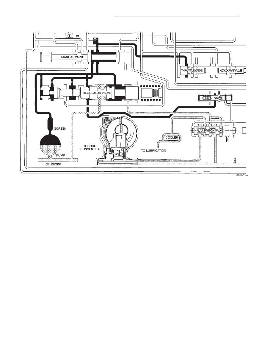
all other gear positions (Fig. 23), fluid flows between
two right side lands to the switch valve and torque
converter. At low pump speeds, the flow is controlled
by the pressure valve groove to reduce pressure to
the torque converter. After the torque converter and
switch valve fill with fluid, the switch valve becomes
the controlling metering device for torque converter
pressure. The regulator valve then begins to control
the line pressure for the other transmission circuits.
The balance of the fluid pressure pushing the valve
to the right and the spring pressure pushing to the

left determines the size of the metering passage at
land #2 (land #1 being at the far right of the valve in
the diagram). As fluid leaks past the land, it moves
into a groove connected to the filter or sump. As the
land meters the fluid to the sump, it causes the pres-
sure to reduce and the spring decreases the size of
the metering passage. When the size of the metering
passage is reduced, the pressure rises again and the
size of the land is increased again. Pressure is regu-
lated by this constant balance of hydraulic and
spring pressure.

Fig. 23 Regulator Valve in Neutral Position

21 - 22

42RE AUTOMATIC TRANSMISSION

WJ

DESCRIPTION AND OPERATION (Continued)

The metering at land #2 establishes the line pres-

sure throughout the transmission. It is varied accord-
ing to changes in throttle position, engine speed, and
transmission condition within a range of 57–94 psi
(except in reverse) (Fig. 24). The regulated line pres-
sure in reverse (Fig. 25) is held at much higher pres-
sures than in the other gear positions: 145–280 psi.

The higher pressure for reverse is achieved by the
manual valve blocking the supply of line pressure to
the reaction area left of land #4. With this pressure
blocked, there is less area for pressure to act on to
balance the force of the spring on the right. This
allows line pressure to push the valve train to the
right, reducing the amount of fluid returned to the
pump’s inlet, increasing line pressure.

Fig. 24 Regulator Valve in Drive Position

WJ

42RE AUTOMATIC TRANSMISSION

21 - 23

DESCRIPTION AND OPERATION (Continued)

Fig. 25 Regulator Valve in Reverse Position

21 - 24

42RE AUTOMATIC TRANSMISSION

WJ

DESCRIPTION AND OPERATION (Continued)

KICKDOWN VALVE

When the throttle valve is as far over to the left as

it can go, the maximum line pressure possible will
enter the throttle pressure circuit. In this case, throt-
tle pressure will equal line pressure. With the kick-
down valve (Fig. 26) pushed into the bore as far as it
will go, fluid initially flows through the annular
groove of the 2–3 shift valve (which will be in the
direct drive position to the right).

After passing the annular groove, the fluid is

routed to the spring end of the 2–3 shift valve. Fluid
pressure reacting on the area of land #1 overcomes
governor pressure, downshifting the 2–3 shift valve
into the kickdown, or second gear stage of operation.
The valve is held in the kickdown position by throttle
pressure routed from a seated check ball (#2). Again,
if vehicle speed is low enough, throttle pressure will
also push the 1–2 shift valve left to seat its governor
plug, and downshift to drive breakaway.

Fig. 26 Kickdown Valve–Wide Open Throttle

WJ

42RE AUTOMATIC TRANSMISSION

21 - 25

DESCRIPTION AND OPERATION (Continued)


Content   ..  408  409  410  411   ..