Jeep Grand Cherokee WJ. Manual - part 409


  Index      Jeep     Jeep Grand Cherokee WJ - service repair manual 2001 year


Search            


Content   ..  407  408  409  410   ..


Jeep Grand Cherokee WJ. Manual - part 409


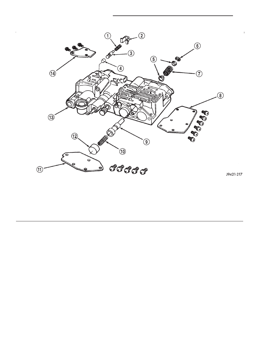
Fig. 19 Shuttle and Boost Valve Locations

1 – SPRING
2 – RETAINER
3 – BOOST VALVE
4 – BOOST VALVE PLUG
5 – SPRING GUIDES
6 – E-CLIP
7 – SHUTTLE VALVE SECONDARY SPRING

8 – SHUTTLE VALVE COVER
9 – SHUTTLE VALVE
10 – SHUTTLE VALVE PRIMARY SPRING
11 – GOVERNOR PLUG COVER
12 – THROTTLE PLUG
13 – UPPER HOUSING
14 – BOOST VALVE COVER

21 - 18

42RE AUTOMATIC TRANSMISSION

WJ

DESCRIPTION AND OPERATION (Continued)

Fig. 20 Upper Housing Shift Valve and Pressure Plug Locations

1 – UPPER HOUSING
2 – 1–2 SHIFT VALVE AND SPRING
3 – 2–3 SHIFT VALVE AND SPRING
4 – 2–3 THROTTLE PLUG
5 – LIMIT VALVE HOUSING
6 – LIMIT VALVE COVER
7 – LIMIT VALVE AND SPRING

8 – RETAINER
9 – 1–2 SHIFT CONTROL VALVE AND SPRING
10 – PRESSURE PLUG COVER
11 – LINE PRESSURE PLUG
12 – PLUG SLEEVE
13 – THROTTLE PRESSURE SPRING AND PLUG

WJ

42RE AUTOMATIC TRANSMISSION

21 - 19

DESCRIPTION AND OPERATION (Continued)

Fig. 21 Lower Housing Shift Valves and Springs

1 – 3-4 ACCUMULATOR HOUSING
2 – 3-4 SHIFT VALVE AND SPRING
3 – PLUG
4 – SPRING RETAINER
5 – CONVERTER CLUTCH VALVE AND SPRING
6 – CONVERTER CLUTCH TIMING VALVE AND SPRING
7 – OVERDRIVE SEPARATOR PLATE
8 – CASE CONNECTOR
9 – CONVERTER CLUTCH SOLENOID
10 – OVERDRIVE SOLENOID

11 – TIMING VALVE COVER
12 – PLUG
13 – 3-4 TIMING VALVE AND SPRING
14 – LOWER HOUSING
15 – ACCUMULATOR END PLATE
16 – 3-4 ACCUMULATOR PISTON AND SPRING
17 – E-CLIP
18 – 3-4 QUICK FILL SPRING AND VALVE
19 – SOLENOID GASKET
20 – HARNESS

21 - 20

42RE AUTOMATIC TRANSMISSION

WJ

DESCRIPTION AND OPERATION (Continued)

OPERATION

NOTE: Refer to the Hydraulic Schematics for a
visual aid in determining valve location, operation
and design.

REGULATOR VALVE

The pressure regulator valve is needed to control

the hydraulic pressure within the system and reduce
the amount of heat produced in the fluid. The pres-
sure regulator valve is located in the valve body near
the manual valve. The pressure regulator valve train
controls the maximum pressure in the lines by
metering the dumping of fluid back into the sump.
Regulated pressure is referred to as “line pressure.”

The regulator valve (Fig. 22) has a spring on one

end that pushes the valve to the left. This closes a
dump (vent) that is used to lower pressure. The clos-
ing of the dump will cause the oil pressure to
increase. Oil pressure on the opposite end of the
valve pushes the valve to the right, opening the
dump and lowering oil pressure. The result is spring
pressure working against oil pressure to maintain
the oil at specific pressures. With the engine run-
ning, fluid flows from the pump to the pressure reg-
ulator valve, manual valve, and the interconnected
circuits. As fluid is sent through passages to the reg-
ulator valve, the pressure pushes the valve to the
right against the large spring. It is also sent to the
reaction areas on the left side of the throttle pressure
plug and the line pressure plug. With the gear selec-
tor in the park position, fluid recirculates through
the regulator and manual valves back to the sump.

Fig. 22 Regulator Valve in Park Position

WJ

42RE AUTOMATIC TRANSMISSION

21 - 21

DESCRIPTION AND OPERATION (Continued)


Content   ..  407  408  409  410   ..