Jeep Grand Cherokee WJ. Manual - part 384


  Index      Jeep     Jeep Grand Cherokee WJ - service repair manual 2001 year


Search            


Content   ..  382  383  384  385   ..


Jeep Grand Cherokee WJ. Manual - part 384


OXYGEN SENSOR

REMOVAL

Never apply any type of grease to the oxygen

sensor electrical connector, or attempt any sol-
dering of the sensor wiring harness. For sensor
operation, it must have a comparison source of
oxygen from outside the exhaust system. This
fresh air is supplied to the sensor through its
pigtail wiring harness.

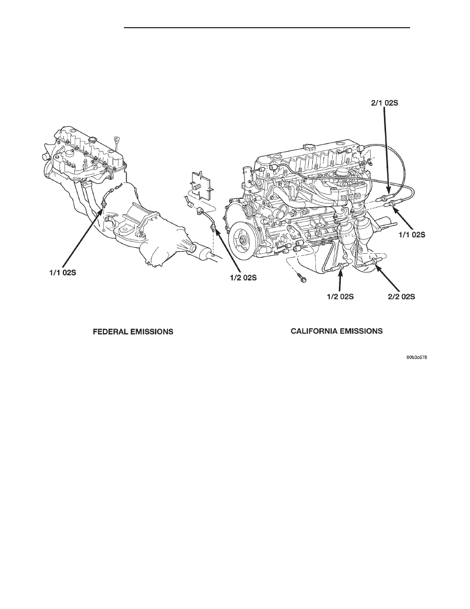
Oxygen sensor (O2S) locations are shown in (Fig.

35) and (Fig. 36).

WARNING: THE EXHAUST MANIFOLD, EXHAUST
PIPES AND CATALYTIC CONVERTER(S) BECOME
VERY HOT DURING ENGINE OPERATION. ALLOW
ENGINE TO COOL BEFORE REMOVING OXYGEN
SENSOR.

(1) Raise and support vehicle.
(2) Disconnect O2S pigtail harness from main wir-

ing harness.

(3) If equipped, disconnect sensor wire harness

mounting clips from engine or body.

CAUTION: When disconnecting sensor electrical
connector, do not pull directly on wire going into
sensor.

(4) Remove O2S sensor with an oxygen sensor

removal and installation tool.

INSTALLATION

Threads of new oxygen sensors are factory coated

with anti-seize compound to aid in removal. DO
NOT add any additional anti-seize compound to
threads of a new oxygen sensor.

Fig. 35 Oxygen Sensor Locations—4.0L Engine

14 - 56

FUEL SYSTEM

WJ

REMOVAL AND INSTALLATION (Continued)

(1) Install O2S sensor. Tighten to 30 N·m (22 ft.

lbs.) torque.

(2) Connect O2S sensor wire connector to main

wiring harness.

(3) If

equipped,

connect

sensor

wire

harness

mounting clips to engine or body. When Equipped:
The O2S pigtail harness must be clipped and/or
bolted

back

to

their

original

positions

on

engine or body to prevent mechanical damage
to wiring.
.

(4) Lower vehicle.

RADIATOR FAN COOLING RELAY

REMOVAL

The Pulse Width Modulated (PWM) cooling fan

relay is located below the right headlamp behind the
bumper fascia (Fig. 37).

(1) Remove front bumper and grill assembly.

(2) Remove 1 support bolt near front of reservoir

(Fig. 37).

(3) Remove 2 reservoir mounting bolts.
(4) Remove reservoir from vehicle to gain access to

vacuum hose (Fig. 38). Disconnect vacuum hose from
reservoir fitting at rear of reservoir.

(5) Disconnect electrical connector at relay (Fig.

39).

(6) Remove 2 relay mounting bolts (Fig. 39) and

remove relay.

INSTALLATION

(1) Position relay to body and install 2 bolts.

Tighten bolts to 3 N·m (25 in. lbs.) torque.

(2) Connect electrical connector to relay.
(3) Connect vacuum hose to reservoir.
(4) Install reservoir and tighten 2 bolts to 3 N·m

(25 in. lbs.) torque.

(5) Install front bumper and grill assembly.

Fig. 36 Oxygen Sensor Locations—4.7L V-8 Engine

WJ

FUEL SYSTEM

14 - 57

REMOVAL AND INSTALLATION (Continued)

AIR CLEANER ELEMENT (FILTER)

REMOVAL

(1) Unlatch four clips retaining air cleaner cover to

air cleaner housing (Fig. 40) or (Fig. 41).

(2) Lift cover up and position to the side.
(3) Remove air cleaner element.

INSTALLATION

(1) Clean inside of air cleaner housing before

installing new element.

(2) Install air cleaner element into housing.
(3) Latch clips and clamp cover down to secure. Be

sure air cleaner cover is properly seated to air
cleaner housing.

Fig. 37 Radiator Cooling Fan Relay Location

1 – RADIATOR FAN RELAY
2 – VACUUM RESERVOIR
3 – BOLT
4 – RIGHT FRONT FENDER

Fig. 38 Vacuum Reservoir Removal/Installation

1 – VACUUM HOSE
2 – RADIATOR
3 – VACUUM RESERVOIR

Fig. 39 Radiator Cooling Fan Relay Removal/

Installation

1 – ELECTRICAL CONNECTOR
2 – RADIATOR FAN RELAY
3 – MOUNTING BOLTS (2)

14 - 58

FUEL SYSTEM

WJ

REMOVAL AND INSTALLATION (Continued)

AIR CLEANER HOUSING/RESONATOR/DUCTS

REMOVAL

(1) Disconnect air cleaner cover-to-air duct clamp

(Fig. 40) or (Fig. 41).

(2) Disconnect air duct at housing.
(3)

Each of the 3 air cleaner housing mount-

ing bolts is attached with 2 nuts (an upper nut
and lower nut). DO NOT REMOVE BOLTS. To
prevent stripping bolts, only remove lower
nuts. The lower housing nuts are located under
left front inner fender (Fig. 40) or (Fig. 41).

(a) To gain access to lower nuts, raise vehicle.
(b) Remove clips retaining rubber inner fender

shield.

(c) Pry back shield enough to gain access to

lower nuts.

(d) Remove 3 nuts.

(e) Remove air cleaner assembly from vehicle.

(4) 4.0L Engine: If resonator is to be removed, dis-

connect breather tube at resonator, disconnect air
duct clamp at resonator (Fig. 40) and remove 1 reso-
nator mounting bolt. Remove resonator from throttle
body by loosening clamp (Fig. 42).

(5) 4.7L V-8 Engine: If resonator is to be removed,

disconnect breather tube at resonator, disconnect air
duct clamp at resonator (Fig. 41) and remove 2 reso-
nator mounting bolts (at sides of resonator). Remove
resonator from throttle body by loosening clamp at
throttle body.

INSTALLATION

(1) Position air cleaner assembly to body and

install 3 nuts. Tighten nuts to 10 N·m (93 in. lbs.)
torque. To prevent excessive vibration transmit-
ted through housing, the nuts must be properly
torqued. Do not overtighten nuts.

Fig. 40 Air Cleaner Assembly —4.0L Engine

1 – RESONATOR BOLTS
2 – CLAMPS
3 – AIR DUCT
4 – AIR CLEANER COVER
5 – CLIPS
6 – HOUSING
7 – HOUSING BOLTS (3)
8 – LOWER HOUSING NUTS (3)
9 – RESONATOR

Fig. 41 Air Cleaner Assembly —4.7L V-8 Engine

1 – AIR DUCT
2 – CLAMPS
3 – AIR CLEANER COVER
4 – CLIPS
5 – HOUSING
6 – HOUSING BOLTS (3)
7 – LOWER HOUSING NUTS (3)
8 – RESONATOR BOLTS
9 – RESONATOR

WJ

FUEL SYSTEM

14 - 59

REMOVAL AND INSTALLATION (Continued)


Content   ..  382  383  384  385   ..