Jeep Grand Cherokee WJ. Manual - part 312


  Index      Jeep     Jeep Grand Cherokee WJ - service repair manual 2001 year


Search            


Content   ..  310  311  312  313   ..


Jeep Grand Cherokee WJ. Manual - part 312


CYLINDER COMBUSTION PRESSURE LEAKAGE
TEST

The combustion pressure leakage test provides an

accurate means for determining engine condition.

Combustion pressure leakage testing will detect:
• Exhaust and intake valve leaks (improper seat-

ing).

• Leaks between adjacent cylinders or into water

jacket.

• Any causes for combustion/compression pressure

loss.

(1) Check the coolant level and fill as required. DO

NOT install the radiator cap.

(2) Start and operate the engine until it attains

normal operating temperature, then turn the engine
OFF.

(3) Remove the spark plugs.
(4) Remove the oil filler cap.

(5) Remove the air cleaner.
(6) Calibrate the tester according to the manufac-

turer’s instructions. The shop air source for testing
should maintain 483 kPa (70 psi) minimum, 1,379
kPa (200 psi) maximum and 552 kPa (80 psi) recom-
mended.

(7) Perform the test procedures on each cylinder

according to the tester manufacturer’s instructions.
While testing, listen for pressurized air escaping
through the throttle body, tailpipe and oil filler cap
opening. Check for bubbles in the radiator coolant.

All gauge pressure indications should be equal,

with no more than 25% leakage.

FOR EXAMPLE: At 552 kPa (80 psi) input pres-

sure, a minimum of 414 kPa (60 psi) should be main-
tained in the cylinder.

Refer to the Cylinder Combustion Pressure Leak-

age Test Diagnosis chart.

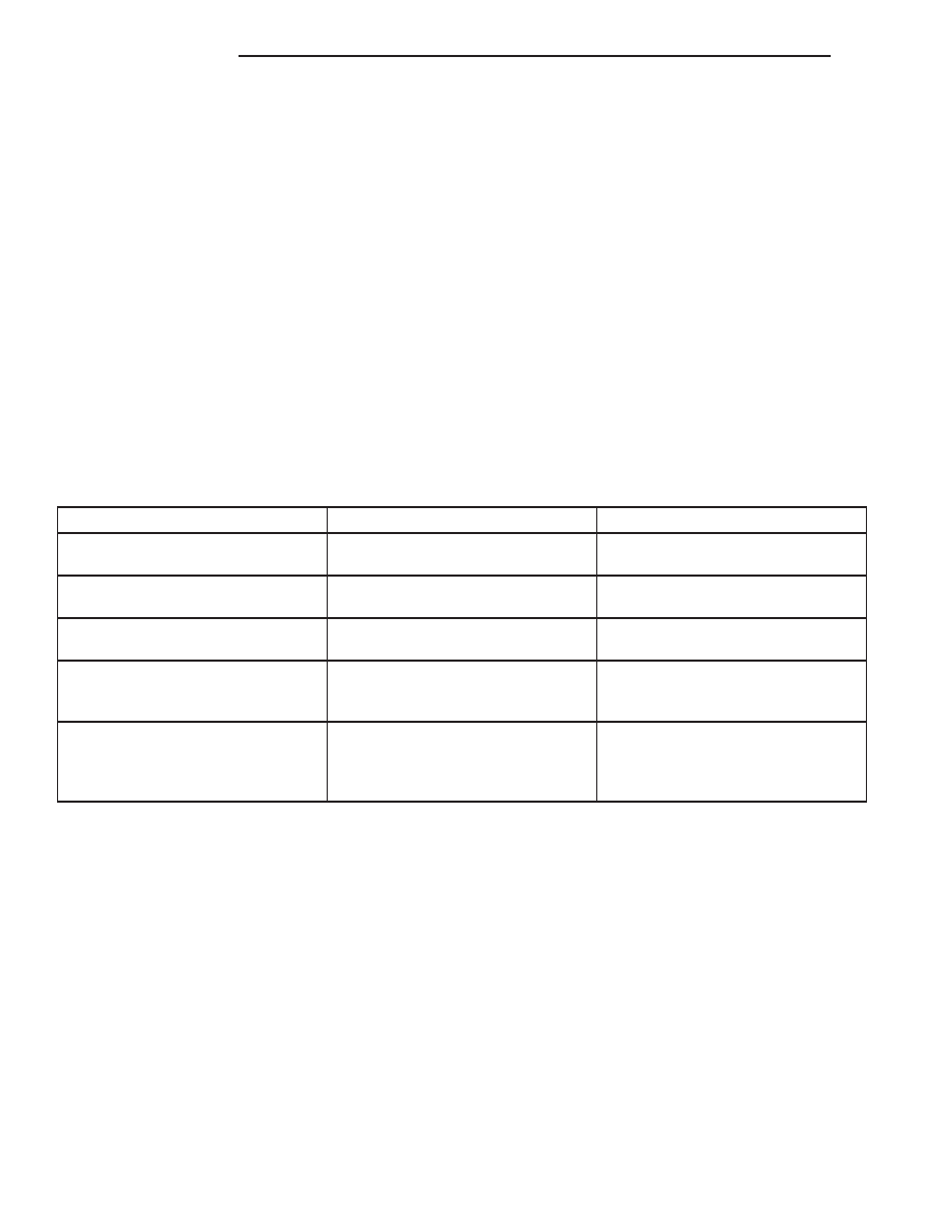
CYLINDER COMBUSTION PRESSURE LEAKAGE DIAGNOSIS CHART

CONDITION

POSSIBLE CAUSE

CORRECTION

AIR ESCAPES THROUGH
THROTTLE BODY

Intake valve bent, burnt, or not
seated properly

Inspect valve and valve seat.
Reface or replace, as necessary

AIR ESCAPES THROUGH
TAILPIPE

Exhaust valve bent, burnt, or not
seated properly

Inspect valve and valve seat.
Reface or replace, as necessary

AIR ESCAPES THROUGH
RADIATOR

Head gasket leaking or cracked
cylinder head or block

Remove cylinder head and inspect.
Replace defective part

MORE THAN 50% LEAKAGE
FROM ADJACENT CYLINDERS

Head gasket leaking or crack in
cylinder head or block between
adjacent cylinders

Remove cylinder head and inspect.
Replace gasket, head, or block as
necessary

MORE THAN 25% LEAKAGE AND
AIR ESCAPES THROUGH OIL
FILLER CAP OPENING ONLY

Stuck or broken piston rings;
cracked piston; worn rings and/or
cylinder wall

Inspect for broken rings or piston.
Measure ring gap and cylinder
diameter, taper and out-of-round.
Replace defective part as necessary

ENGINE OIL LEAK INSPECTION

Begin with a thorough visual inspection of the

engine, particularly at the area of the suspected leak.
If an oil leak source is not readily identifiable, the
following steps should be followed:

(1) Do not clean or degrease the engine at this

time because some solvents may cause rubber to
swell, temporarily stopping the leak.

(2) Add an oil soluble dye (use as recommended by

manufacturer). Start the engine and let idle for
approximately 15 minutes. Check the oil dipstick to
make sure the dye is thoroughly mixed as indicated
with a bright yellow color under a black light.

(3) Using a black light, inspect the entire engine

for fluorescent dye, particularly at the suspected area
of oil leak. If the oil leak is found and identified,
repair per service manual instructions.

(4) If dye is not observed, drive the vehicle at var-

ious speeds for approximately 24km (15 miles), and
repeat inspection.

(4)

If the oil leak source is not positively

identified at this time, proceed with the air leak
detection test method.

Air Leak Detection Test Method

(1) Disconnect the breather cap to air cleaner hose

at the breather cap end. Cap or plug breather cap
nipple.

(2) Remove the PCV valve from the cylinder head

cover. Cap or plug the PCV valve grommet.

(3) Attach an air hose with pressure gauge and

regulator to the dipstick tube.

CAUTION: Do not subject the engine assembly to
more than 20.6 kpa (3 PSI) of test pressure.

9 - 14

4.0L ENGINE

WJ

DIAGNOSIS AND TESTING (Continued)

(4) Gradually apply air pressure from 1 psi to 2.5

psi maximum while applying soapy water at the sus-
pected source. Adjust the regulator to the suitable
test pressure that provide the best bubbles which
will pinpoint the leak source. If the oil leak is
detected and identified, repair per service manual
procedures.

(5) If the leakage occurs at the rear oil seal area,

refer to the section, Inspection for Rear Seal Area
Leak.

(6) If no leaks are detected, turn off the air supply

and remove the air hose and all plugs and caps.
Install the PCV valve and breather cap hose.

(7) Clean the oil off the suspect oil leak area using

a suitable solvent. Drive the vehicle at various
speeds approximately 24 km (15 miles). Inspect the
engine for signs of an oil leak by using a black light.

INSPECTION FOR REAR SEAL AREA LEAKS

Since it is sometimes difficult to determine the

source of an oil leak in the rear seal area of the
engine, a more involved inspection is necessary. The
following steps should be followed to help pinpoint
the source of the leak.

If the leakage occurs at the crankshaft rear oil seal

area:

(1) Disconnect the battery.
(2) Raise the vehicle.
(3) Remove torque converter or clutch housing

cover and inspect rear of block for evidence of oil.
Use a black light to check for the oil leak:

(a) Circular spray pattern generally indicates

seal leakage or crankshaft damage.

(b) Where leakage tends to run straight down,

possible causes are a porous block, distributor seal,
camshaft bore cup plugs oil galley pipe plugs, oil
filter runoff, and main bearing cap to cylinder
block mating surfaces.
(4) If no leaks are detected, pressurize the crank-

case as outlined in the, Inspection (Engine oil Leaks
in general)

CAUTION: Do not exceed 20.6 kPa (3 psi).

(5) If the leak is not detected, very slowly turn the

crankshaft and watch for leakage. If a leak is
detected between the crankshaft and seal while
slowly turning the crankshaft, it is possible the
crankshaft seal surface is damaged. The seal area on
the crankshaft could have minor nicks or scratches
that can be polished out with emery cloth.

CAUTION: Use extreme caution when crankshaft
polishing is necessary to remove minor nicks and
scratches. The crankshaft seal flange is especially
machined to complement the function of the rear oil
seal.

(6) For bubbles that remain steady with shaft

rotation, no further inspection can be done until dis-
assembled.

ENGINE OIL PRESSURE

(1) Disconnect connector and remove oil pressure

sending unit.

(2) Install Oil Pressure Line and Gauge Tool

C-3292 or equivalent. Start engine and record pres-
sure. Refer to Oil Pressure in Engine Specifications
for the correct pressures.

SERVICE PROCEDURES

FORM-IN-PLACE GASKETS & SEALERS

There are numerous places where form-in-place

gaskets are used on the engine. Care must be taken
when

applying

form-in-place

gaskets

to

assure

obtaining the desired results. Do not use form-in-
place gasket material unless specified. 
Bead size,
continuity, and location are of great importance. Too
thin a bead can result in leakage while too much can
result in spill-over which can break off and obstruct
fluid feed lines. A continuous bead of the proper
width is essential to obtain a leak-free gasket.

There are numerous types of form-in-place gasket

materials that are used in the engine area. Mopar

t

Engine RTV GEN II, Mopar

t ATF-RTV, and Mopart

Gasket Maker gasket materials, each have different
properties and can not be used in place of the other.

MOPAR

ENGINE RTV GEN II

Mopar

t Engine RTV GEN II is used to seal com-

ponents exposed to engine oil. This material is a spe-
cially designed black silicone rubber RTV that
retains

adhesion

and

sealing

properties

when

exposed to engine oil. Moisture in the air causes the
material to cure. This material is available in three
ounce tubes and has a shelf life of one year. After one
year this material will not properly cure. Always
inspect the package for the expiration date before
use.

MOPAR

ATF RTV

Mopar

t ATF RTV is a specifically designed black

silicone rubber RTV that retains adhesion and seal-
ing properties to seal components exposed to auto-
matic

transmission

fluid,

engine

coolants,

and

moisture. This material is available in three ounce
tubes and has a shelf life of one year. After one year
this material will not properly cure. Always inspect
the package for the expiration date before use.

MOPAR

GASKET MAKER

Mopar

t Gasket Maker is an anaerobic type gasket

material. The material cures in the absence of air
when squeezed between two metallic surfaces. It will
not cure if left in the uncovered tube. The anaerobic

WJ

4.0L ENGINE

9 - 15

DIAGNOSIS AND TESTING (Continued)

material is for use between two machined surfaces.
Do not use on flexible metal flanges.

MOPAR

GASKET SEALANT

Mopar

t Gasket Sealant is a slow drying, perma-

nently soft sealer. This material is recommended for
sealing threaded fittings and gaskets against leakage
of oil and coolant. Can be used on threaded and
machined parts under all temperatures. This mate-
rial is used on engines with multi-layer steel (MLS)
cylinder head gaskets. This material also will pre-
vent corrosion. Mopar

t Gasket Sealant is available in

a 13 oz. aerosol can or 4oz./16 oz. can w/applicator.

FORM-IN-PLACE GASKET AND SEALER
APPLICATION

Assembling parts using a form-in-place gasket

requires care but it’s easier then using precut gas-
kets.

Mopar

t Gasket Maker material should be applied

sparingly 1 mm (0.040 in.) diameter or less of sealant
to one gasket surface. Be certain the material sur-
rounds each mounting hole. Excess material can eas-
ily be wiped off. Components should be torqued in
place within 15 minutes. The use of a locating dowel
is recommended during assembly to prevent smear-
ing material off the location.

Mopar

t Engine RTV GEN II or ATF RTV gasket

material should be applied in a continuous bead
approximately 3 mm (0.120 in.) in diameter. All
mounting holes must be circled. For corner sealing, a
3.17 or 6.35 mm (1/8 or 1/4 in.) drop is placed in the
center of the gasket contact area. Uncured sealant
may be removed with a shop towel. Components
should be torqued in place while the sealant is still
wet to the touch (within 10 minutes). The usage of a
locating dowel is recommended during assembly to
prevent smearing material off the location.

Mopar

t Gasket Sealant in an aerosol can should be

applied using a thin, even coat sprayed completely
over both surfaces to be joined, and both sides of a
gasket. Then proceed with assembly. Material in a
can w/applicator can be brushed on evenly over the
sealing surfaces. Material in an aerosol can should be
used on engines with multi-layer steel gaskets.

ENGINE GASKET SURFACE PREPARATION

To ensure engine gasket sealing, proper surface

preparation must be performed, especially with the
use of aluminum engine components and multi-layer
steel cylinder head gaskets.

Never use the following to clean gasket surfaces:
• Metal scraper

• Abrasive pad or paper to clean cylinder block

and head

• High speed power tool with an abrasive pad or a

wire brush (Fig. 15)

NOTE: Multi-Layer

Steel

(MLS)

head

gaskets

require a scratch free sealing surface.

Only use the following for cleaning gasket surfaces:
• Solvent or a commercially available gasket

remover

• Plastic or wood scraper (Fig. 15)

• Drill motor with 3M Rolocy Bristle Disc (white

or yellow) (Fig. 15)

CAUTION: Excessive

pressure

or

high

RPM

(beyond the recommended speed), can damage the
sealing surfaces. The mild (white, 120 grit) bristle
disc is recommended. If necessary, the medium
(yellow, 80 grit) bristle disc may be used on cast
iron surfaces with care.

ENGINE PERFORMANCE

To provide best vehicle performance and lowest

vehicle emissions, it is most important that the
tune-up be done accurately. Use the specifications
listed on the Vehicle Emission Control Information
label found on the engine compartment hood.

(1) Test battery specific gravity. Add water, if nec-

essary. Clean and tighten battery connections.

(2) Test cranking amperage draw (refer to Group

8B, Battery/Starter for the proper procedure).

(3) Tighten the intake manifold bolts (refer to

Group 11, Exhaust System and Intake Manifold for
the proper specifications).

(4) Perform cylinder compression test:

CAUTION: DO NOT overspeed the engine.

Fig. 15 Proper Tool Usage For Surface Preparation

1 – ABRASIVE PAD
2 – 3M ROLOC

Y

BRISTLE DISC

3 – PLASTIC/WOOD SCRAPER

9 - 16

4.0L ENGINE

WJ

SERVICE PROCEDURES (Continued)

(a) Check engine oil level and add oil, if neces-

sary.

(b) Drive the vehicle until engine reaches nor-

mal operating temperature.

(c) Select a route free from traffic and other

forms of congestion, observe all traffic laws and
briskly accelerate through the gears several times.
The higher engine speed may help clean out valve
seat deposits which can prevent accurate compres-
sion readings.

(d) Disconnect electrical connectors from coil

towers and then remove coil towers.

(e) Remove all spark plugs from engine. As

spark plugs are being removed, check electrodes for
abnormal firing indicators - fouled, hot, oily, etc.
Record cylinder number of spark plug for future
reference.

(f) Be sure throttle blades are fully open during

the compression check.

(g) Insert compression gauge adaptor into the

No.1 spark plug hole. Crank engine until maxi-
mum pressure is reached on gauge. Record this
pressure as No.1 cylinder pressure.

(h) Repeat for all remaining cylinders.
(i) Record the findings and compare them with

the compression standards listed under Engine
Specifications.

(j) If cylinder(s) have abnormally low compres-

sion pressures, repeat procedure.

(k) If the same cylinder(s) repeat an abnormally

low reading, it could indicate the existence of a
problem in the cylinder.

NOTE: The recommended compression pressures
are to be used only as a guide to diagnosing engine
problems. An engine should NOT be disassembled
to determine the cause of low compression unless
some malfunction is present.

(5) Clean or replace spark plugs as necessary.

Adjust gap (refer to Group 8D, Ignition System for
gap adjustment and torque).

(6) Perform a combustion analysis.
(7) Test fuel pump for pressure (refer to Group 14,

Fuel System for the proper specifications).

(8) Inspect air filter element (refer to Group 0,

Lubrication and Maintenance for the proper proce-
dure).

(9) Inspect crankcase ventilation system (refer to

Group 0, Lubrication and Maintenance for the proper
procedure).

(10) For emission controls refer to Group 25, Emis-

sion Controls System for service procedures.

(11) Inspect and adjust accessory belt drives (refer

to Group 7, Cooling System for the proper adjust-
ments).

(12) Road test vehicle as a final test.

HONING CYLINDER BORES

Before honing, stuff plenty of clean shop towels

under the bores and over the crankshaft to keep
abrasive materials from entering the crankshaft
area.

(1) Used carefully, the Cylinder Bore Sizing Hone

C-823 equipped with 220 grit stones, is the best tool
for this job. In addition to deglazing, it will reduce
taper and out-of-round as well as removing light
scuffing, scoring or scratches. Usually a few strokes
will clean up a bore and maintain the required lim-
its.

CAUTION: DO NOT use rigid type hones to remove
cylinder wall glaze.

(2) Deglazing of the cylinder walls may be done if

the cylinder bore is straight and round. Use a cylin-
der surfacing hone, Honing Tool C-3501, equipped
with 280 grit stones (C-3501-3810). 20-60 strokes,
depending on the bore condition, will be sufficient to
provide a satisfactory surface. Using honing oil
C-3501-3880 or a light honing oil available from
major oil distributors.

CAUTION: DO NOT use engine or transmission oil,
mineral spirits or kerosene.

(3) Honing should be done by moving the hone up

and down fast enough to get a crosshatch pattern.
The hone marks should INTERSECT at 50° to 60°
for proper seating of rings (Fig. 16).

(4) A controlled hone motor speed between 200 and

300 RPM is necessary to obtain the proper cross-
hatch angle. The number of up and down strokes per
minute can be regulated to get the desired 50° to 60°

Fig. 16 Cylinder Bore Crosshatch Pattern

1 – CROSSHATCH PATTERN
2 – INTERSECT ANGLE

WJ

4.0L ENGINE

9 - 17

SERVICE PROCEDURES (Continued)


Content   ..  310  311  312  313   ..