Jeep Grand Cherokee WJ. Manual - part 310
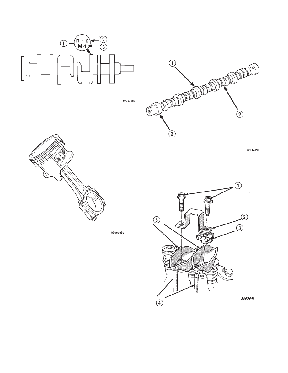
CAMSHAFT
DESCRIPTION
The camshaft is made of gray cast iron with twelve
machined lobes and four bearing journals. When the
camshaft rotates the lobes actuate the tappets and
push rods, forcing upward on the rocker arms which
applies downward force on the valves.
ROCKER ARM
DESCRIPTION
The rocker arms are made of stamped steel and
have a operational ratio of 1.6:1. When the push rods
are forced upward by the camshaft lobes the push
rod presses upward on the rocker arms, the rocker
arms pivot, forcing downward pressure on the valves
forcing the valves to move downward and off from
their seats (Fig. 8).
Fig. 5 Crankshaft with Select Fit Marking Location
1 – 1/4” LETTERS
2 – (ROD)
3 – (MAIN)
Fig. 6 Piston and Connecting Rod Assembly
Fig. 7 Camshaft—Typical
1 – CAMSHAFT
2 – LOBES
3 – BEARING JOURNAL
Fig. 8 Rocker Arms 4.0L Engine
1 – CAPSCREWS
2 – BRIDGE
3 – PIVOT ASSEMBLY
4 – PUSH RODS
5 – ROCKER ARMS
9 - 6
4.0L ENGINE
WJ
DESCRIPTION AND OPERATION (Continued)