Jeep Grand Cherokee WJ. Manual - part 108


  Index      Jeep     Jeep Grand Cherokee WJ - service repair manual 2001 year


Search            


Content   ..  106  107  108  109   ..


Jeep Grand Cherokee WJ. Manual - part 108


INSTRUMENT PANEL ASSEMBLY

WARNING: ON VEHICLES EQUIPPED WITH AIR-
BAGS,

REFER

TO

GROUP

8M

-

PASSIVE

RESTRAINT SYSTEMS BEFORE ATTEMPTING ANY
STEERING

WHEEL,

STEERING

COLUMN,

OR

INSTRUMENT PANEL COMPONENT DIAGNOSIS OR
SERVICE. FAILURE TO TAKE THE PROPER PRE-
CAUTIONS COULD RESULT IN ACCIDENTAL AIR-
BAG DEPLOYMENT AND POSSIBLE PERSONAL
INJURY.

REMOVAL

NOTE: Before starting this procedure, be certain to
turn the steering wheel until the front wheels are in
the straight-ahead position.

(1) Disconnect and isolate the battery negative

cable.

(2) Remove the trim from the right and left A-pil-

lars. Refer to A-Pillar Trim in the Removal and
Installation section of Group 23 - Body for the proce-
dures.

(3) Remove the top cover from the instrument

panel. Refer to Instrument Panel Top Cover in the
Removal and Installation section of this group for the
procedures.

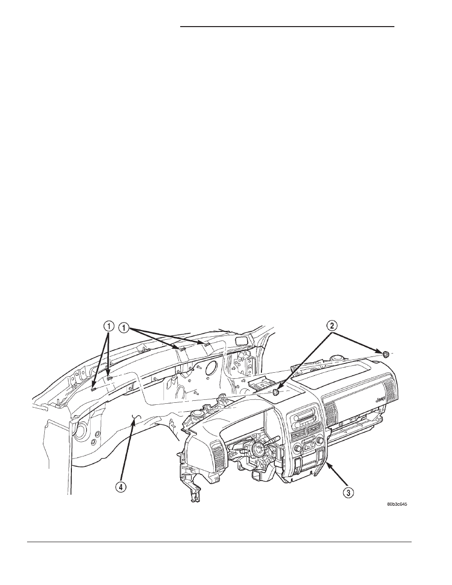
(4) Remove the four nuts that secure the instru-

ment panel to the studs on the dash panel near the
windshield fence line (Fig. 32).

(5) Remove the scuff plates from the right and left

front door sills. Refer to Front Door Scuff Plate in
the Removal and Installation section of Group 23 -
Body for the procedures.

(6) Remove the trim panels from the right and left

inner cowl sides. Refer to Front Door Scuff Plate
in the Removal and Installation section of Group 23 -
Body for the procedures.

(7) Remove the console from the floor panel trans-

mission tunnel. Refer to Floor Console in the
Removal and Installation section of Group 23 - Body
for the procedures.

(8) Remove the fuse cover from the junction block.

Refer to Instrument Panel Fuse Cover in the
Removal and Installation section of this group for the
procedures.

(9) Remove the cluster bezel from the instrument

panel. Refer to Cluster Bezel in the Removal and
Installation section of this group for the procedures.

(10) Remove the steering column opening cover

from the instrument panel. Refer to Steering Col-
umn Opening Cover 
in the Removal and Installa-
tion section of this group for the procedures.

(11) Remove the steering column bracket from the

instrument panel steering column support bracket.
Refer to Instrument Panel Steering Column

Fig. 32 Instrument Panel to Dash Panel Mounting

1 – STUD (4)
2 – NUT (4)

3 – INSTRUMENT PANEL
4 – DASH PANEL

8E - 34

INSTRUMENT PANEL SYSTEMS

WJ

REMOVAL AND INSTALLATION (Continued)

Bracket in the Removal and Installation section of
this group for the procedures.

(12) Remove the screw that secures the lower tilt-

ing steering column shroud to the steering column
multifunction switch mounting housing (Fig. 33).

(13) Unsnap the two halves of the tilting steering

column shroud from each other and remove both
halves from the steering column.

(14) Disconnect the instrument panel wire harness

connectors from the following steering column compo-
nents (Fig. 34):

• the two lower clockspring connector receptacles

• the left multifunction switch receptacle

• the right multifunction switch receptacle

• the two ignition switch receptacles

• the shifter interlock solenoid receptacle

• if the vehicle is so equipped, the Sentry Key

Immobilizer Module (SKIM) receptacle.

(15) Turn the ignition switch to the On position,

then release and remove the shifter interlock cable
connector from the ignition lock housing receptacle.

(16) Turn the ignition switch back to the Lock

position to prevent steering wheel rotation and the
loss of clockspring centering following steering col-
umn removal.

(17) Remove the bolt that secures the coupler to

the lower steering column shaft (Fig. 35).

Fig. 33 Steering Column Shrouds Remove/Install

1 – UPPER TILTING COLUMN SHROUD
2 – FIXED COLUMN SHROUD
3 – LOWER TILTING COLUMN SHROUD
4 – SCREW

Fig. 34 Steering Column Connections

1 – LEFT MULTIFUNCTION SWITCH CONNECTOR
2 – LOWER CLOCKSPRING CONNECTORS
3 – RIGHT MULTIFUNCTION SWITCH CONNECTOR
4 – SHIFTER INTERLOCK CABLE CONNECTOR
5 – SHIFTER INTERLOCK SOLENOID CONNECTOR
6 – IGNITION SWITCH CONNECTOR RECEPTACLES
7 – SKIM CONNECTOR

Fig. 35 Steering Column Mounting

1 – COLUMN MOUNTING NUTS
2 – COUPLER BOLT

WJ

INSTRUMENT PANEL SYSTEMS

8E - 35

REMOVAL AND INSTALLATION (Continued)

(18) Remove the four nuts that secure the steering

column to the studs on the instrument panel steering
column support bracket.

(19) Remove the steering column from the instru-

ment panel. Be certain that the steering wheel is
locked and secured from rotation to prevent the loss
of clockspring centering.

(20) Disconnect the left and right body wire har-

ness bulkhead connectors, the Ignition Off Draw
(IOD) wire harness connector and the fused B(+) wire
harness connector from the connector receptacles of
the junction block (Fig. 36).

(21) Disconnect the instrument panel wire harness

connectors from the following floor panel transmis-
sion tunnel components (Fig. 37):

• the airbag control module connector receptacle

• the park brake switch terminal

• the transmission shifter connector receptacle.
(22) Remove the two nuts that secure the instru-

ment panel wire harness ground eyelets to the studs
on the floor panel transmission tunnel in front of and
behind the airbag control module.

(23) Disengage

the

retainers

that

secure

the

instrument panel wire harness to the floor panel
transmission tunnel.

(24) Remove the instrument panel to center floor

tunnel bracket from the instrument panel and the
floor panel transmission tunnel. Refer to Instru-
ment Panel to Center Floor Tunnel Bracket 
in
the Removal and Installation section of this group for
the procedures.

(25) Remove the one screw that secures the driver

side floor duct to the heater and air conditioner hous-
ing near the driver side of the floor panel transmis-
sion tunnel and remove the duct from the housing.

(26) If the vehicle is equipped with the manual

heating and air conditioning system, disconnect the
vacuum harness connector located near the driver
side of the floor panel transmission tunnel behind
the driver side floor duct.

(27) Remove the one screw that secures the instru-

ment panel steering column support bracket to the
driver side end of the heater and air conditioner
housing (Fig. 38).

(28) Remove the one screw that secures the instru-

ment panel steering column support bracket to the
intermediate bracket on the driver side dash panel
(Fig. 39).

(29) Remove the nut that secures the instrument

panel steering column support bracket to the stud on
the driver side cowl plenum panel (Fig. 40).

(30) Remove the two screws that secure the instru-

ment panel to the driver side cowl side inner panel
(Fig. 41).

(31) Remove the end cap from the instrument

panel. Refer to Instrument Panel End Cap in the
Removal and Installation section of this group for the
procedures.

Fig. 36 Junction Block Connections

1 – SNAP CLIPS
2 – SCREW
3 – BULKHEAD CONNECTOR
4 – LEFT BODY WIRE HARNESS
5 – IOD CONNECTOR
6 – FUSED B+ CONNECTOR
7 – RIGHT BODY WIRE HARNESS
8 – SCREW
9 – BULKHEAD CONNECTOR
10 – JUNCTION BLOCK

8E - 36

INSTRUMENT PANEL SYSTEMS

WJ

REMOVAL AND INSTALLATION (Continued)

(32) Remove the lower right center bezel from the

instrument

panel.

Refer

to

Instrument

Panel

Lower Right Center Bezel in the Removal and
Installation section of this group for the procedures.

(33) Disconnect the instrument panel wire harness

bulkhead connector from the lower cavity of the
inline connector on the passenger side cowl side
inner panel (Fig. 42).

(34) Disconnect

the

two

halves

of

the

radio

antenna coaxial cable connector near the right cowl
side inner panel under the end of the instrument
panel.

(35) Disconnect the two instrument panel wire

harness connectors from the two heater and air con-
ditioner housing connectors located near the blower
motor on the passenger side end of the housing (Fig.
43).

(36) Remove the two screws that secure the pas-

senger side instrument panel structural duct to the
heater and air conditioner housing (Fig. 44).

(37) Remove the two screws that secure the instru-

ment panel to the passenger side cowl side inner
panel (Fig. 45).

Fig. 37 Floor Panel Transmission Tunnel Connections

1 – AIRBAG CONTROL MODULE CONNECTOR
2 – PARK BRAKE SWITCH CONNECTOR
3 – AIRBAG CONTROL MODULE
4 – NUT (2)
5 – STUD
6 – GROUND EYELET

7 – RETAINER
8 – STUD
9 – GROUND EYELET
10 – INSTRUMENT PANEL WIRE HARNESS
11 – TRANSMISSION SHIFTER CONNECTOR

Fig. 38 Driver Side Instrument Panel to Heater-A/C

Housing Mounting

1 – HEATER AND AIR CONDITIONER HOUSING
2 – FLOOR DUCT
3 – INSTRUMENT PANEL STEERING COLUMN SUPPORT BRACKET
4 – SCREW

WJ

INSTRUMENT PANEL SYSTEMS

8E - 37

REMOVAL AND INSTALLATION (Continued)


Content   ..  106  107  108  109   ..