Jeep Grand Cherokee WJ. Manual - part 106


  Index      Jeep     Jeep Grand Cherokee WJ - service repair manual 2001 year


Search            


Content   ..  104  105  106  107   ..


Jeep Grand Cherokee WJ. Manual - part 106


GLOVE BOX LATCH

WARNING: ON VEHICLES EQUIPPED WITH AIR-
BAGS,

REFER

TO

GROUP

8M

-

PASSIVE

RESTRAINT SYSTEMS BEFORE ATTEMPTING ANY
STEERING

WHEEL,

STEERING

COLUMN,

OR

INSTRUMENT PANEL COMPONENT DIAGNOSIS OR
SERVICE. FAILURE TO TAKE THE PROPER PRE-
CAUTIONS COULD RESULT IN ACCIDENTAL AIR-
BAG DEPLOYMENT AND POSSIBLE PERSONAL
INJURY.

REMOVAL

(1) Disconnect and isolate the battery negative

cable.

(2) Roll down the glove box from the instrument

panel. Refer to Glove Box - Roll Down in the
Removal and Installation section of this group for the
procedures.

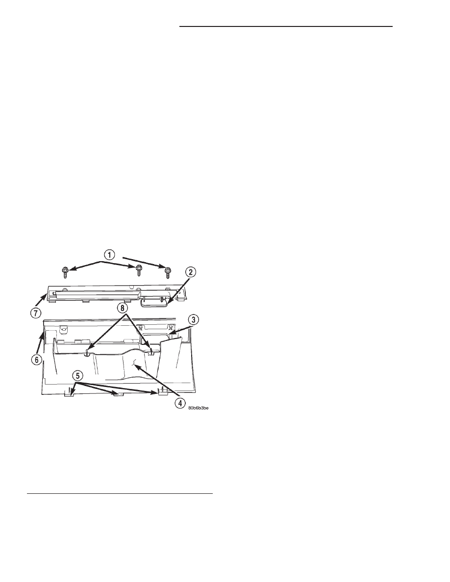
(3) Remove the three screws that secure the glove

box latch to the inner glove box door (Fig. 22).

(4) Lift up on the latch handle on the outer glove

box door far enough to loosen the latch assembly on
the inner glove box door.

(5) Remove the latch unit from the inner glove box

door.

INSTALLATION

(1) Position the latch unit to the inner glove box

door.

(2) Guide the latch handle into the latch handle

pocket on the outer glove box door.

(3) Install and tighten the three screws that secure

the glove box latch to the inner glove box door.
Tighten the screws to 2.2 N·m (20 in. lbs.).

(4) Roll the glove box back up into the instrument

panel. Refer to Glove Box - Roll Down in the
Removal and Installation section of this group for the
procedures.

(5) Reconnect the battery negative cable.

INSTRUMENT PANEL END CAP

WARNING: ON VEHICLES EQUIPPED WITH AIR-
BAGS,

REFER

TO

GROUP

8M

-

PASSIVE

RESTRAINT SYSTEMS BEFORE ATTEMPTING ANY
STEERING

WHEEL,

STEERING

COLUMN,

OR

INSTRUMENT PANEL COMPONENT DIAGNOSIS OR
SERVICE. FAILURE TO TAKE THE PROPER PRE-
CAUTIONS COULD RESULT IN ACCIDENTAL AIR-
BAG DEPLOYMENT AND POSSIBLE PERSONAL
INJURY.

REMOVAL

(1) Disconnect and isolate the battery negative

cable.

(2) Open the glove box.
(3) Remove the one screw that secures the out-

board end of the end cap to the instrument panel top
pad (Fig. 23).

(4) Remove the three screws that secure the end

cap to the instrument panel glove box opening.

(5) Pull the end cap straight back from the instru-

ment panel to disengage the one snap clip that
secures it to the receptacle in the instrument panel
structural duct.

(6) Remove the end cap from the instrument

panel.

INSTALLATION

(1) Be certain that the glove box catch bumper is

installed in the mounting hole nearest the outboard
end of the end cap extension over the instrument
panel upper glove box opening reinforcement.

(2) Position the end cap to the instrument panel.

Be certain that the end of the end cap extension near
the center of the upper glove box opening reinforce-
ment is positioned underneath the end of the exten-
sion from the lower right center bezel.

(3) Align the snap clip on the end cap with the

receptacle on the instrument panel structural duct.

Fig. 22 Glove Box Latch Remove/Install

1 – SCREW (3)
2 – LATCH HANDLE
3 – LATCH HANDLE POCKET
4 – BIN
5 – HINGE HOOKS
6 – DOOR
7 – GLOVE BOX LATCH
8 – STOPS

8E - 26

INSTRUMENT PANEL SYSTEMS

WJ

REMOVAL AND INSTALLATION (Continued)

(4) Press firmly on the instrument panel end cap

over the snap clip location until the snap clip is fully
engaged in its receptacle.

(5) Install and tighten the three screws that secure

the end cap to the instrument panel glove box open-
ing. Tighten the screws to 2.2 N·m (20 in. lbs.).

(6) Install and tighten the one screw that secures

the outboard end of the end cap to the instrument
panel top pad. Tighten the screw to 2.2 N·m (20 in.
lbs.).

(7) Close the glove box.
(8) Reconnect the battery negative cable.

INSTRUMENT PANEL LOWER RIGHT CENTER
BEZEL

WARNING: ON VEHICLES EQUIPPED WITH AIR-
BAGS,

REFER

TO

GROUP

8M

-

PASSIVE

RESTRAINT SYSTEMS BEFORE ATTEMPTING ANY
STEERING

WHEEL,

STEERING

COLUMN,

OR

INSTRUMENT PANEL COMPONENT DIAGNOSIS OR
SERVICE. FAILURE TO TAKE THE PROPER PRE-
CAUTIONS COULD RESULT IN ACCIDENTAL AIR-
BAG DEPLOYMENT AND POSSIBLE PERSONAL
INJURY.

REMOVAL

(1) Disconnect and isolate the battery negative

cable.

(2) Open the glove box.

(3) Remove the three screws that secure the lower

right center bezel to the instrument panel glove box
opening (Fig. 24).

(4) Pull the lower right center bezel straight back

from the instrument panel to disengage the two snap
clips that secure it to the receptacles in the instru-
ment panel top pad.

(5) Remove the lower right center bezel from the

instrument panel.

INSTALLATION

(1) Be certain that the glove box catch bumper is

installed in the mounting hole nearest the inboard
end of the lower right center bezel extension over the
instrument panel upper glove box opening reinforce-
ment.

(2) Position the lower right center bezel to the

instrument panel. Be certain that the end of the
lower right center bezel extension near the center of
the upper glove box opening reinforcement is posi-
tioned on top of the end of the extension from the
end cap.

(3) Align the snap clips on the lower right center

bezel with the receptacles in the instrument panel
top pad.

(4) Press firmly on the lower right center bezel

over each of the snap clip locations until the snap
clips are fully engaged in their receptacles.

(5) Install and tighten the three screws that secure

the lower right center bezel to the instrument panel

Fig. 23 Instrument Panel End Cap Remove/Install

1 – INSTRUMENT PANEL TOP PAD
2 – END CAP
3 – SCREW (4)
4 – BUMPER
5 – LOWER RIGHT CENTER BEZEL

Fig. 24 Instrument Panel Lower Right Center Bezel

Remove/Install

1 – INSTRUMENT PANEL TOP PAD
2 – END CAP
3 – SCREWS (3)
4 – BUMPER
5 – LOWER RIGHT CENTER BEZEL

WJ

INSTRUMENT PANEL SYSTEMS

8E - 27

REMOVAL AND INSTALLATION (Continued)

glove box opening. Tighten the screws to 2.2 N·m (20
in. lbs.).

(6) Close the glove box.
(7) Reconnect the battery negative cable.

GLOVE BOX LATCH STRIKER

WARNING: ON VEHICLES EQUIPPED WITH AIR-
BAGS, REFER TO GROUP 8M - PASSIVE RESTRAINT
SYSTEMS BEFORE ATTEMPTING ANY STEERING
WHEEL,

STEERING

COLUMN,

OR

INSTRUMENT

PANEL COMPONENT DIAGNOSIS OR SERVICE. FAIL-
URE TO TAKE THE PROPER PRECAUTIONS COULD
RESULT IN ACCIDENTAL AIRBAG DEPLOYMENT
AND POSSIBLE PERSONAL INJURY.

REMOVAL

(1) Disconnect and isolate the battery negative

cable.

(2) If the inboard glove box latch striker is being

serviced, remove the lower right center bezel from
the instrument panel. Refer to Instrument Panel
Lower Right Center Bezel 
in the Removal and
Installation section of this group for the procedures.
If the outboard glove box latch striker is being ser-
viced, remove the end cap from the instrument panel.
Refer to Instrument Panel End Cap in the
Removal and Installation section of this group for the
procedures.

(3) Remove the one screw that secures the upper

mounting flange of the glove box latch striker to the
instrument panel structural duct at either side of the
glove box opening (Fig. 25).

(4) Pull the upper mounting flange of the glove box

latch striker downward to disengage the hook forma-
tion on the lower end of the striker from the mount-
ing hole in the instrument panel structural duct.

(5) Remove the glove box latch striker from the

instrument panel.

INSTALLATION

(1) Position the glove box latch striker to the

instrument panel.

(2) Engage the hook formation on the lower end of

the glove box latch striker in the mounting hole in
the instrument panel structural duct.

(3) Roll the upper mounting flange of the glove box

latch striker upward until it is flush with the instru-
ment panel structural duct on either side of the glove
box opening.

(4) Install and tighten the screw that secures the

upper mounting flange of the glove box latch striker
to the instrument panel structural duct. Tighten the
screw to 2.2 N·m (20 in. lbs.).

(5) If the inboard glove box latch striker was ser-

viced, install the lower right center bezel onto the

instrument

panel.

Refer

to

Instrument

Panel

Lower Right Center Bezel in the Removal and
Installation section of this group for the procedures.
If the outboard glove box latch striker was serviced,
install the end cap onto the instrument panel. Refer
to Instrument Panel End Cap in the Removal and
Installation section of this group for the procedures.

(6) Reconnect the battery negative cable.

GLOVE BOX LAMP AND SWITCH

WARNING: ON VEHICLES EQUIPPED WITH AIR-
BAGS, REFER TO GROUP 8M - PASSIVE RESTRAINT
SYSTEMS BEFORE ATTEMPTING ANY STEERING
WHEEL,

STEERING

COLUMN,

OR

INSTRUMENT

PANEL COMPONENT DIAGNOSIS OR SERVICE. FAIL-
URE TO TAKE THE PROPER PRECAUTIONS COULD
RESULT IN ACCIDENTAL AIRBAG DEPLOYMENT
AND POSSIBLE PERSONAL INJURY.

REMOVAL

(1) Disconnect and isolate the battery negative

cable.

(2) Roll down the glove box from the instrument

panel. Refer to Glove Box - Roll Down in the
Removal and Installation section of this group for the
procedures.

(3) Remove the lower right center bezel from the

instrument

panel.

Refer

to

Instrument

Panel

Lower Right Center Bezel in the Removal and
Installation section of this group for the procedures.

Fig. 25 Glove Box Latch Striker Remove/Install

1 – SCREW
2 – GLOVE BOX LATCH STRIKER
3 – INSTRUMENT PANEL TOP PAD

8E - 28

INSTRUMENT PANEL SYSTEMS

WJ

REMOVAL AND INSTALLATION (Continued)

(4) Reach through the glove box opening and

behind the glove box opening upper reinforcement in
the instrument panel to access and depress the
retaining latches on the top and bottom of the glove
box lamp and switch housing.

(5) While holding the retaining latches depressed,

push the glove box lamp and switch out through the
mounting hole in the instrument panel glove box
opening upper reinforcement (Fig. 26).

(6) Pull the glove box lamp and switch out from

the mounting hole far enough to access the wire har-
ness connector.

(7) Disconnect the instrument panel wire harness

connector from the glove box lamp and switch con-
nector receptacle.

(8) Remove the glove box lamp and switch from

the instrument panel.

INSTALLATION

(1) Position the glove box lamp and switch to the

instrument panel.

(2) Reconnect the instrument panel wire harness

connector to the glove box lamp and switch connector
receptacle.

(3) Feed the instrument panel wire harness back

into the glove box lamp and switch mounting hole in
the glove box opening upper reinforcement.

(4) Align the glove box lamp and switch housing

with the mounting hole in the instrument panel
glove box opening upper reinforcement.

(5) Push the glove box lamp and switch into the

mounting hole in the instrument panel glove box

opening upper reinforcement until the retaining
latches are fully engaged.

(6) Install the lower right center bezel onto the

instrument

panel.

Refer

to

Instrument

Panel

Lower Right Center Bezel in the Removal and
Installation section of this group for the procedures.

(7) Roll the glove box back up into the instrument

panel. Refer to Glove Box - Roll Down in the
Removal and Installation section of this group for the
procedures.

(8) Reconnect the battery negative cable.

INSTRUMENT PANEL TOP COVER

WARNING: ON VEHICLES EQUIPPED WITH AIR-
BAGS, REFER TO GROUP 8M - PASSIVE RESTRAINT
SYSTEMS BEFORE ATTEMPTING ANY STEERING
WHEEL,

STEERING

COLUMN,

OR

INSTRUMENT

PANEL COMPONENT DIAGNOSIS OR SERVICE. FAIL-
URE TO TAKE THE PROPER PRECAUTIONS COULD
RESULT IN ACCIDENTAL AIRBAG DEPLOYMENT
AND POSSIBLE PERSONAL INJURY.

REMOVAL

(1) Disconnect and isolate the battery negative

cable.

(2) Using a trim stick or another suitable wide

flat-bladed tool, gently pry the rear edge (farthest
from the windshield) of the top cover up and away
from the instrument panel far enough to disengage
the four snap clip retainers from their receptacles in
the instrument panel top pad (Fig. 27).

Fig. 26 Glove Box Lamp and Switch Remove/Install

1 – GLOVE BOX OPENING UPPER REINFORCEMENT
2 – WIRE HARNESS CONNECTOR
3 – GLOVE BOX LAMP & SWITCH
4 – LATCH
5 – MOUNTING HOLE

Fig. 27 Instrument Panel Top Cover Remove/Install

1 – ULTRA LIGHT SENSOR PLUG
2 – SEAL
3 – INSTRUMENT PANEL TOP COVER

WJ

INSTRUMENT PANEL SYSTEMS

8E - 29

REMOVAL AND INSTALLATION (Continued)


Content   ..  104  105  106  107   ..