Content .. 1006 1007 1008 1009 ..
Jeep Grand Cherokee WJ. Manual - part 1008
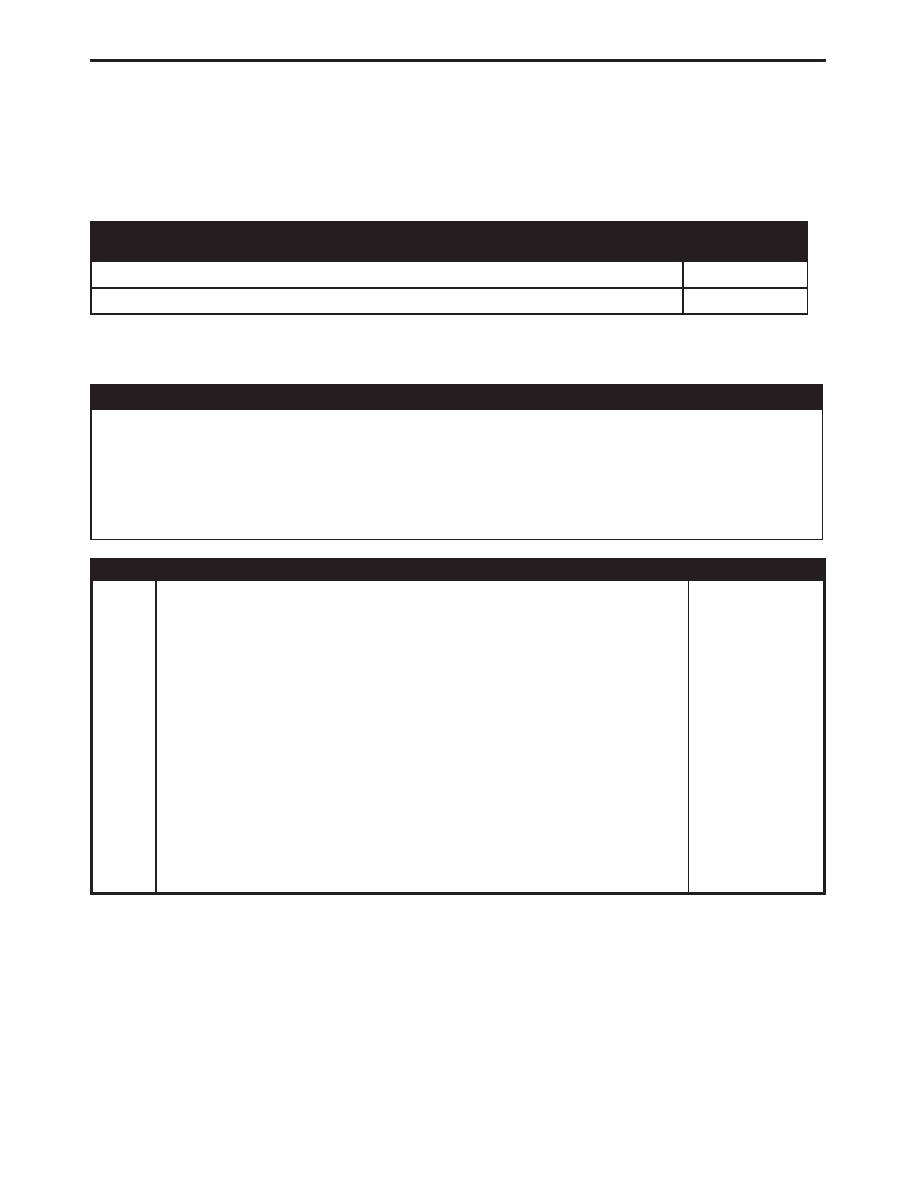
Symptom:
*CHECKING MINIMUM AIRFLOW
APPLICABILITY
START AT
TEST
4.0L MPI I-6
1
4.7L ENGINE(EVA)/4SPD A/T 45RFE(DG4)
2
POSSIBLE CAUSES
CHECKING THE MINIMUM AIRFLOW
THROTTLE PLATE/LINKAGE BINDING
VACUUM LEAK
THROTTLE BODY
THROTTLE BODY DIRTY
TEST
ACTION
APPLICABILITY
1
Start engine and bring to operating temperature. Be sure all accessories are off
before performing this test.
Shut off engine and remove air duct and air resonator box from top of throttle body.
Disconnect rear CCV breather tube at intake manifold fitting. Let CCV tube hang
disconnected at side of engine.
Attach a short piece of rubber hose to special tool 6714. Install this hose/tool
assembly to intake manifold fitting.
Connect the DRBIII
t.
Start the Engine.
Using the DRBIII
t, run the Minimum Air Flow test.
The DRBIII
t will count down to stabilize the idle rpm and display the minimum air
flow idle rpm. The idle rpm should be between 500 and 900 rpm. If the idle speed is
outside of these specifications, replace the throttle body.
Is the engine rpm between 500 and 900 rpm?
4.0L MPI I-6
Yes
→
Test Complete.
No
→
Replace the throttle body.
Perform POWERTRAIN VERIFICATION TEST VER - 5.
249
DRIVEABILITY - GAS