Jeep Grand Cherokee WJ. Manual - part 67


  Index      Jeep     Jeep Grand Cherokee WJ - service repair manual 2001 year


Search            


Content   ..  65  66  67  68   ..


Jeep Grand Cherokee WJ. Manual - part 67


WARNING: CONSTANT TENSION HOSE CLAMPS
ARE USED ON MOST COOLING SYSTEM HOSES.
WHEN REMOVING OR INSTALLING, USE ONLY
TOOLS DESIGNED FOR SERVICING THIS TYPE OF
CLAMP, SUCH AS SPECIAL CLAMP TOOL (NUMBER
6094). SNAP-ON CLAMP TOOL (NUMBER HPC-20)
MAY BE USED FOR LARGER CLAMPS. ALWAYS
WEAR SAFETY GLASSES WHEN SERVICING CON-
STANT TENSION CLAMPS.

CAUTION: A number or letter is stamped into the
tongue of constant tension clamps. If replacement
is necessary, use only an original equipment clamp
with matching number or letter.

(4) If water pump is being replaced, do not unbolt

fan blade assembly from thermal viscous fan drive.

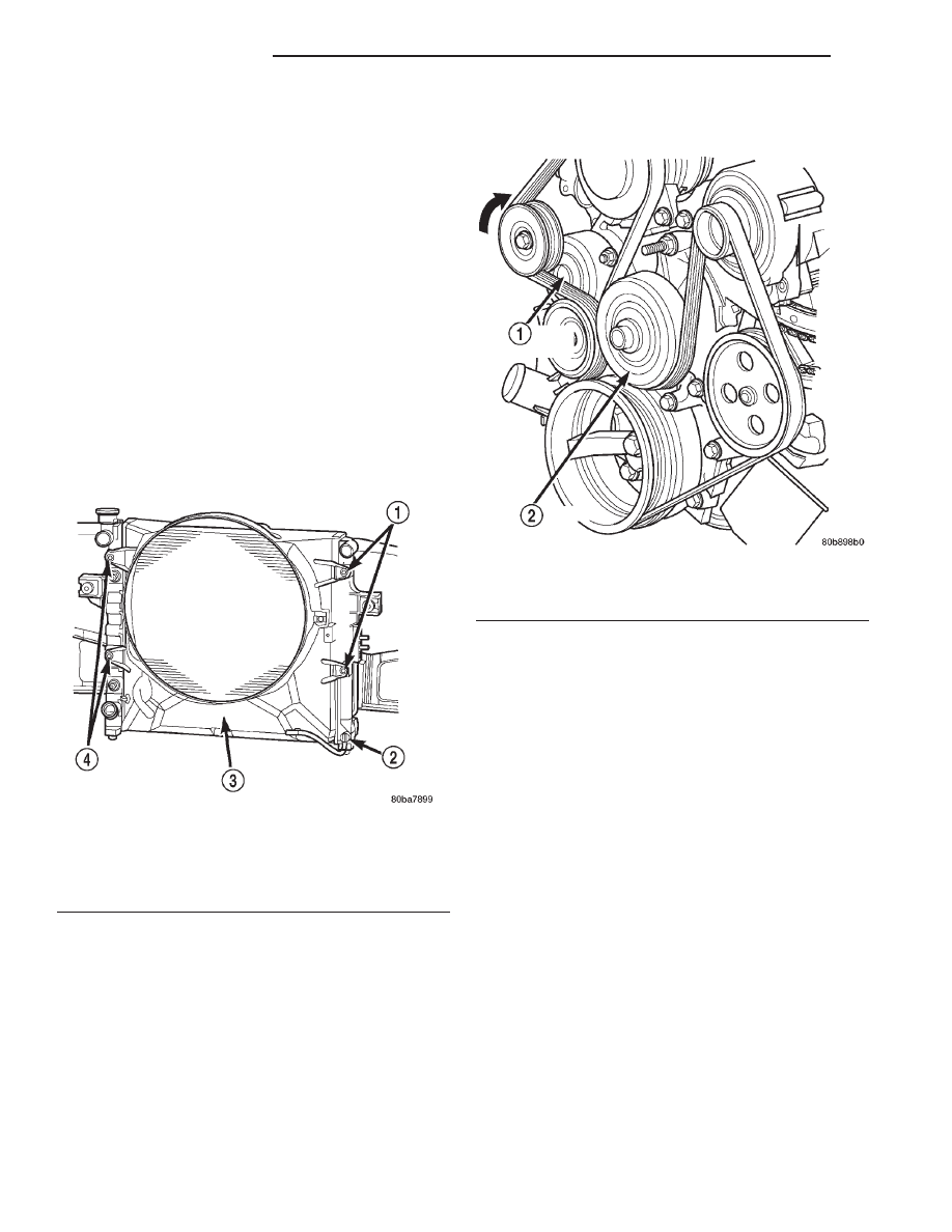
(5) Remove two fan shroud-to-radiator nuts (Fig.

33). Do not attempt to remove fan shroud at this
time.

(6) Remove fan shroud and fan blade/viscous fan

drive assembly from vehicle as a complete unit.

(7) After removing fan blade/viscous fan drive

assembly, do not place thermal viscous fan drive in
horizontal position. If stored horizontally, silicone
fluid in viscous fan drive could drain into its bearing
assembly and contaminate lubricant.

(8) Remove accessory drive belt as follows: The

drive belt is equipped with a spring loaded automatic
belt tensioner. Relax tension from belt by rotating
tensioner clockwise (as viewed from front) (Fig. 34).

When all belt tension has been relaxed, remove
accessory drive belt.

(9) Remove lower radiator hose clamp and remove

lower hose at water pump.

(10) Remove seven water pump mounting bolts

and one stud bolt.

CAUTION: Do not pry water pump at timing chain
case/cover. The machined surfaces may be dam-
aged resulting in leaks.

(11) Remove water pump and gasket. Discard gas-

ket.

INSTALLATION

(1) Clean gasket mating surfaces.
(2) Using a new gasket, position water pump and

install mounting bolts as shown. (Fig. 35). Tighten
water pump mounting bolts to 54 N·m (40 ft. lbs.)
torque.

(3) Spin water pump to be sure that pump impel-

ler does not rub against timing chain case/cover.

(4) Connect radiator lower hose to water pump.
(5) Relax tension from belt tensioner (Fig. 34).

Install drive belt.

Fig. 33 Fan Shroud Mounting Hardware

1 – SHROUD FASTENERS
2 – DRAIN COCK
3 – RADIATOR FAN SHROUD
4 – SHROUD FASTENERS

Fig. 34 Automatic Belt Tensioner—4.7L

1 – AUTOMATIC TENSIONER
2 – WATER PUMP PULLEY

7 - 30

COOLING SYSTEM

WJ

REMOVAL AND INSTALLATION (Continued)

CAUTION: When installing the serpentine acces-
sory drive belt, belt must be routed correctly. If not,
engine may overheat due to water pump rotating in
wrong direction. Refer to (Fig. 36) for correct belt
routing. Or, refer to the Belt Routing Label located
in the engine compartment. The correct belt with
correct length must be used.

(6) Position fan shroud and fan blade/viscous fan

drive assembly to vehicle as a complete unit.

(7) Be sure the upper and lower portions of the fan

shroud are firmly connected. All air must flow
through the radiator.

(8) Install two fan shroud-to-radiator nuts (Fig. 33).
(9) Be sure of at least 25 mm (1.0 inches) between

tips of fan blades and fan shroud.

(10) Install fan blade/viscous fan drive assembly to

water pump shaft.

(11) Fill cooling system. Refer to Refilling the Cool-

ing System in this group.

(12) Connect negative battery cable.
(13) Start and warm the engine. Check for leaks.

THERMOSTAT—4.0L ENGINE

REMOVAL

WARNING: DO

NOT

LOOSEN

THE

RADIATOR

DRAINCOCK WITH THE SYSTEM HOT AND PRES-
SURIZED. SERIOUS BURNS FROM THE COOLANT
CAN OCCUR.

Do not waste reusable coolant. If the solution is

clean, drain the coolant into a clean container for
reuse.

(1) Drain the coolant from the radiator until the

level is below the thermostat housing.

WARNING: CONSTANT TENSION HOSE CLAMPS
ARE USED ON MOST COOLING SYSTEM HOSES.
WHEN REMOVING OR INSTALLING, USE ONLY
TOOLS DESIGNED FOR SERVICING THIS TYPE OF
CLAMP, SUCH AS SPECIAL CLAMP TOOL (NUMBER
6094) (Fig. 49). SNAP-ON CLAMP TOOL (NUMBER
HPC-20) MAY BE USED FOR LARGER CLAMPS.
ALWAYS WEAR SAFETY GLASSES WHEN SERVIC-
ING CONSTANT TENSION CLAMPS.

CAUTION: A number or letter is stamped into the
tongue of constant tension clamps. If replacement
is necessary, use only an original equipment clamp
with matching number or letter.

Fig. 35 Water Pump Installation—4.7L

1 – WATER PUMP
2 – TIMING CHAIN COVER

Fig. 36 Belt Routing 4.7L

1 – GENERATOR
2 – ACCESSORY DRIVE BELT
3 – POWER STEERING
4 – CRANKSHAFT
5 – IDLER
6 – TENSIONER
7 – A/C
8 – WATER PUMP

WJ

COOLING SYSTEM

7 - 31

REMOVAL AND INSTALLATION (Continued)

(2) Remove radiator upper hose and heater hose at

thermostat housing.

(3) Disconnect wiring connector at engine coolant

temperature sensor.

(4) Remove thermostat housing mounting bolts,

thermostat housing, gasket and thermostat (Fig. 37).
Discard old gasket.

(5) Clean the gasket mating surfaces.

INSTALLATION

(1) Install the replacement thermostat so that the

pellet, which is encircled by a coil spring, faces the
engine. All thermostats are marked on the outer
flange to indicate the proper installed position.

(a) Observe the recess groove in the engine cyl-

inder head (Fig. 38).

(b) Position thermostat in groove with arrow and

air bleed hole on outer flange pointing up.
(2) Install replacement gasket and thermostat

housing.

CAUTION: Tightening

the

thermostat

housing

unevenly or with the thermostat out of its recess,
may result in a cracked housing.

(3) Tighten the housing bolts to 22 N·m (16 ft. lbs.)

torque.

(4) Install hoses to thermostat housing.
(5) Install electrical connector to coolant tempera-

ture sensor.

(6) Be sure that the radiator draincock is tightly

closed. Fill the cooling system to the correct level
with the required coolant mixture. Refer to Refilling
Cooling System in this group.

(7) Start and warm the engine. Check for leaks.

THERMOSTAT— 4.7L ENGINE

REMOVAL

WARNING: DO NOT LOOSEN RADIATOR DRAIN-
COCK WITH SYSTEM HOT AND PRESSURIZED.
SERIOUS BURNS FROM COOLANT CAN OCCUR.

Do not waste reusable coolant. If solution is clean,

drain coolant into a clean container for reuse.

If thermostat is being replaced, be sure that

replacement is specified thermostat for vehicle model
and engine type.

(1) Disconnect negative battery cable at battery.
(2) Drain cooling system. Refer to Draining Cool-

ing System in this section.

(3) Raise vehicle on hoist.
(4) Remove splash shield.
(5) Remove lower radiator hose clamp and lower

radiator hose at thermostat housing.

(6) Remove thermostat housing mounting bolts,

thermostat housing and thermostat (Fig. 39).

Fig. 37 Thermostat Removal/Installation—4.0L

Engine

1 – LONG BOLT
2 – GASKET
3 – THERMOSTAT
4 – THERMOSTAT HOUSING
5 – SHORT BOLT

Fig. 38 Thermostat Recess—4.0L Engine

1 – GROOVE

7 - 32

COOLING SYSTEM

WJ

REMOVAL AND INSTALLATION (Continued)

INSTALLATION

(1) Clean mating areas of timing chain cover and

thermostat housing.

(2) Install thermostat (spring side down) into recessed

machined groove on timing chain cover (Fig. 39).

(3) Position thermostat housing on timing chain

cover.

(4) Install two housing-to-timing chain cover bolts.

Tighten bolts to 13 N·m (115 in. lbs.) torque.

CAUTION: Housing must be tightened evenly and
thermostat must be centered into recessed groove
in timimg chain cover. If not, it may result in a
cracked housing, damaged timing chain cover
threads or coolant leaks.

(5) Install lower radiator hose on thermostat housing.
(6) Install splash shield.
(7) Lower vehicle.
(8) Fill cooling system. Refer to Refilling Cooling

System in this section.

(9) Connect negative battery cable to battery.
(10) Start and warm the engine. Check for leaks.

RADIATOR FAN SHROUD

REMOVAL

NOTE: The fan can not be removed seperate from
the shroud. Both fan and shroud must be removed
together.

(1) Using special tool 6958 Spanner Wrench and

8346 Adapters, remove the viscous fan from the
water pump (Fig. 40).

(2) Gently lay fan into shroud.
(3) Disconnect the electrical connector for the electric

fan, then disconnect connector from shroud (Fig. 40A).

(4) Disconnect

transmission

cooler

line

from

retaining clip on fan shroud (Fig. 40A).

NOTE: The lower left side mounting bolt can only
be accessed from under vehicle.

Fig. 39 Thermostat and Thermostat Housing 4.7L

1 – THERMOSTAT HOUSING
2 – THERMOSTAT LOCATION

3 – THERMOSTAT AND GASKET
4 – TIMING CHAIN COVER

Fig. 40 Viscous Fan 4.7L Engine

1 – SPECIAL TOOL 6958 SPANNER WRENCH WITH ADAPTER

PINS 8346

2 – FAN

WJ

COOLING SYSTEM

7 - 33

REMOVAL AND INSTALLATION (Continued)

2000 WJ Service Manual
Publication No. 81-370-0047
TSB 26-03-00

March, 2000


Content   ..  65  66  67  68   ..