Jeep Grand Cherokee WJ. Manual - part 65
(6) Start the engine and operate at 2400 rpm.
Within ten minutes the air temperature (indicated on
the dial thermometer) should be up to 93° C (200° F).
Fan drive engagement should have started to occur
at between 91° to 96° C (195° to 205° F). Engage-
ment is distinguishable by a definite increase in fan
flow noise (roaring). The timing light also will indi-
cate an increase in the speed of the fan.
(7) When the air temperature reaches 93° C (200°
F), remove the plastic sheet. Fan drive disengage-
ment should have started to occur at between 62° to
85° C (145° to 185° F). A definite decrease of fan
flow noise (roaring) should be noticed. If not, replace
the defective viscous fan drive unit.
ELECTRIC COOLING FAN
ELECTRIC COOLING FAN AND RELAY DIAGNOSIS
NOTE: Refer to Electrical Group 8W for electric
cooling fan and relay circuit schematic.
The powertrain control module (PCM) will enter a
diagnostic trouble code (DTC) in memory if it detects
a problem in the auxiliary cooling fan relay or circuit.
Refer to Group 25, Emission Control Systems for cor-
rect DTC retrieval procedures.
If the electric cooling fan is inoperative, check the
15A fuse in the junction block and the 40A fuse in
the Power Distribution Center (PDC) with a 12 volt
test lamp or DVOM. Refer to the inside of the PDC
cover for the exact location of the fuse. If fuses are
o.k., refer to Group 8W for electric cooling fan and
relay circuit schematic.
RADIATOR CAP TO FILLER NECK SEAL—
PRESSURE RELIEF CHECK
With radiator cap installed on filler neck, remove
coolant reserve/overflow tank hose from nipple on
filler neck. Connect a hand operated vacuum pump
to nipple. Operate pump until a reading of 124 to 145
kPa (18 to 21 in. Hg) appears on gauge. If the read-
ing stays steady, or drops slightly and then remains
steady, the pressure valve seal is good. Replace radi-
ator cap if reading does not hold.
WARNING: THE
WARNING
WORDS
—DO
NOT
OPEN HOT— ON THE RADIATOR PRESSURE CAP
ARE A SAFETY PRECAUTION. WHEN HOT, PRES-
SURE BUILDS UP IN COOLING SYSTEM. TO PRE-
VENT SCALDING OR INJURY, THE RADIATOR CAP
SHOULD NOT BE REMOVED WHILE THE SYSTEM
IS HOT AND/OR UNDER PRESSURE.
There is no need to remove the radiator cap
except for the following purposes:
• To check and adjust antifreeze freeze point.
• To refill system with new antifreeze.
• For conducting service procedures.
• When checking for leaks.
WARNING: IF VEHICLE HAS BEEN RUN RECENTLY,
WAIT AT LEAST 15 MINUTES BEFORE REMOVING
RADIATOR CAP. WITH A RAG, SQUEEZE RADIATOR
UPPER HOSE TO CHECK IF SYSTEM IS UNDER
PRESSURE. PLACE A RAG OVER THE CAP AND
WITHOUT
PUSHING
DOWN,
ROTATE
CAP
COUNTER-CLOCKWISE
TO
THE
FIRST
STOP.
ALLOW FLUID TO ESCAPE THROUGH OVERFLOW
HOSE
INTO
COOLANT
RESERVE/OVERFLOW
TANK. SQUEEZE RADIATOR UPPER HOSE TO
DETERMINE
WHEN
PRESSURE
HAS
BEEN
RELEASED. WHEN COOLANT AND STEAM STOP
BEING PUSHED INTO TANK AND SYSTEM PRES-
SURE DROPS, REMOVE RADIATOR CAP COM-
PLETELY.
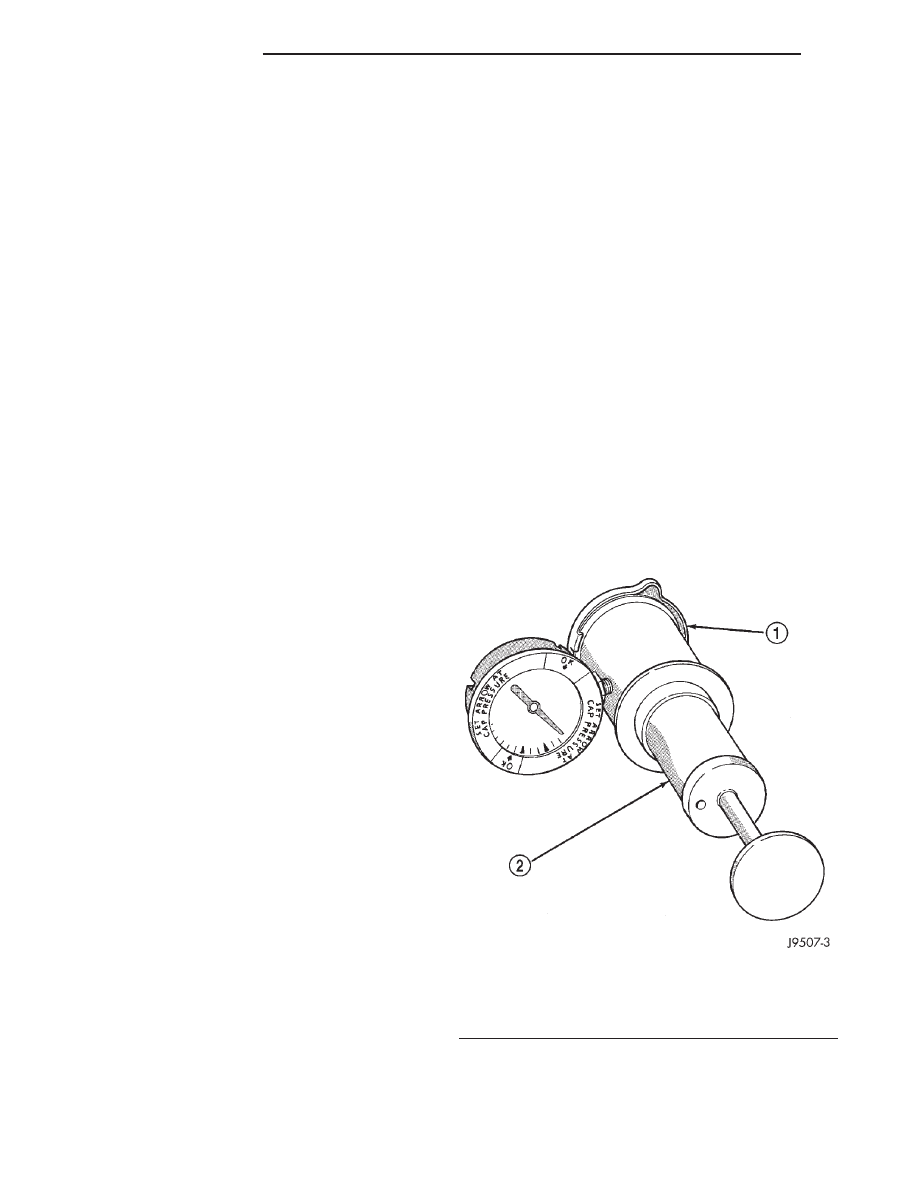
RADIATOR CAP—PRESSURE TESTING
Remove cap from radiator. Be sure that sealing
surfaces are clean. Moisten rubber gasket with water
and install the cap on pressure tester (tool 7700 or
an equivalent) (Fig. 22).
Operate the tester pump and observe the gauge
pointer at its highest point. The cap release pressure
should be 124 to 145 kPa (18 to 21 psi). The cap is
Fig. 22 Pressure Testing Radiator Pressure
Cap—Typical
1 – PRESSURE CAP
2 – TYPICAL COOLING SYSTEM PRESSURE TESTER
7 - 22
COOLING SYSTEM
WJ
DIAGNOSIS AND TESTING (Continued)