Jeep Grand Cherokee WJ. Manual - part 41
 

  Index      Jeep     Jeep Grand Cherokee WJ - service repair manual 2001 year


Search            


Content   ..  39  40  41  42   ..


Jeep Grand Cherokee WJ. Manual - part 41


(3) Insert the retaining plate studs into the brake

backing plate and the axle tube flange.

(4) Install nuts to hold axle retaining plate to axle

tube. Tighten the nuts to 61 N·m (45 ft. lbs.).

(5) Install brake caliper and rotor. Refer to Group

5, Brakes, for proper procedures.

(6) Install wheel and tire.
(7) Check and fill the gear lubricant. Refer to the

Lubricant Specifications for gear lubricant require-
ments.

(8) Lower vehicle.

AXLE SHAFT SEAL AND BEARING

REMOVAL

(1) Remove axle shaft from vehicle.

NOTE: It is normal that the axle bearing race is
loose in the axle tube.

(2) Remove the studs from the axle retaining

plate.

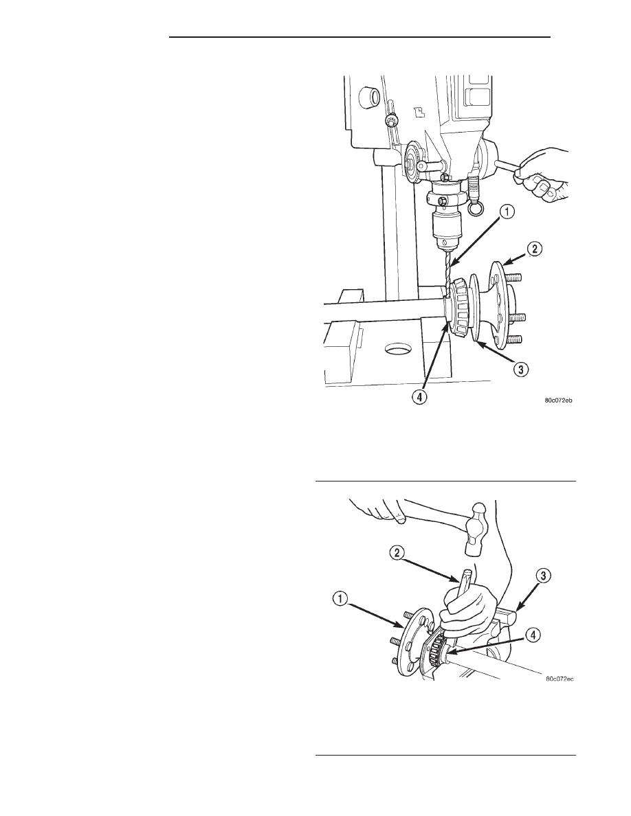
(3) Using a 3/8 in. dia. drill bit, drill a shallow hole

into soft steel axle bearing retaining ring (Fig. 25). If
possible, use a drill depth stop to avoid marking axle.

(4) Using a suitable cold chisel, cut retaining ring

across drilled hole. (Fig. 26)

(5) Slide retaining ring from axle shaft.
(6) Using Splitter 1130 placed between the seal

and bearing and a suitable Arbor Press, press bear-
ing from the axle shaft (Fig. 27).

(7) Slide seal from axle.
(8) Slide retaining plate from axle shaft.

INSTALLATION

(1) Using a suitable straight edge, verify flatness

of axle shaft retaining plate. Replace plate if warped.

(2) Install the studs back into the retaining plate.

If the studs are loose in the plate, replace the retain-
ing plate.

(3) Install retaining plate on axle (Fig. 28).
(4) Apply a coat of multi-purpose grease on sealing

surface of axle seal.

(5) Install seal on axle with cavity away from

retaining plate (Fig. 28).

(6) Lubricate bearing with Mopar

t Wheel Bearing

Grease, or equivalent. Wipe excess grease from the
bearing.

(7) Slide bearing onto axle shaft (Fig. 28).
(8) Using Installer 7913 and shop press, press

bearing onto axle shaft (Fig. 29).

(9) Using Installer 7913 and shop press, press soft

metal retaining ring onto axle shaft (Fig. 30).

(10) Install axle in vehicle.

Fig. 25 Drill Retaining Ring

1 – 3/8 IN DIA DRILL BIT
2 – AXLE
3 – RETAINING PLATE
4 – SOFT METAL RETAINING RING

Fig. 26 Cut Retaining Ring

1 – AXLE
2 – COLD CHISEL
3 – VISE
4 – RETAINING RING

3 - 110

226 RBA AXLE

WJ

REMOVAL AND INSTALLATION (Continued)

Fig. 27 Axle Bearing and Seal Remove

1 – AXLE
2 – PRESS PLATES
3 – BLOCKS
4 – SPECIAL TOOL 1130

Fig. 28 Axle Bearing and Seal Components

1 – RETAINING RING
2 – SEAL
3 – AXLE
4 – RETAINING PLATE
5 – AXLE BEARING

Fig. 29 Press Bearing Onto Axle

1 – PRESS RAM
2 – SPECIAL TOOL 7913
3 – AXLE BEARING
4 – SEAL
5 – RETAINING PLATE
6 – AXLE

Fig. 30 Press Bearing Retaining Ring On Axle

1 – PRESS RAM
2 – AXLE
3 – AXLE BEARING
4 – SPECIAL TOOL 7913
5 – SOFT METAL RETAINING RING

WJ

226 RBA AXLE

3 - 111

REMOVAL AND INSTALLATION (Continued)

DIFFERENTIAL

REMOVAL

(1) Raise and support vehicle.
(2) Remove the lubricant fill hole plug from the

differential housing cover.

(3) Remove the differential housing cover and

allow fluid to drain.

(4) Remove axle shafts.
(5) Note the installation reference letters stamped

on the bearing caps and housing machined sealing
surface (Fig. 31).

(6) Loosen the differential bearing cap bolts.
(7) Position Spreader W–129–B, utilizing some

items from Adapter set 6987, with the tool dowel pins
seated in the locating holes (Fig. 32). Install the hold-
down clamps and tighten the tool turnbuckle finger–
tight.

(8) Install a Pilot Stud C-3288-B at the left side of

the differential housing. Attach Dial Indicator C-3339
to pilot stud. Load the indicator plunger against the
opposite side of the housing (Fig. 33) and zero the
indicator.

CAUTION: Do not spread over 0.38 mm (0.015 in). If
the housing is over–spread, it could be distorted or
damaged.

(9) Spread the housing enough to remove the dif-

ferential case from the housing. Measure the dis-
tance with the dial indicator (Fig. 34).

(10) Remove the dial indicator.
(11) While holding the differential case in position,

remove the differential bearing cap bolts and caps.

(12) Remove the differential from the housing.

Ensure that the differential bearing cups remain in
position on the differential bearings (Fig. 35).

Fig. 31 Bearing Cap Identification

1 – INSTALLATION REFERENCE LETTERS
2 – INSTALLATION REFERENCE LETTERS

Fig. 32 Install Axle Housing Spreader

1 – AXLE HOUSING
2 – DOWEL
3 – SAFETY HOLD DOWN
4 – SPECIAL TOOL W-129–B
5 – TURNBUCKLE

Fig. 33 Install Dial Indicator

1 – SPECIAL TOOL C-3339
2 – DIAL INDICATOR
3 – LEVER ADAPTER
4 – SPECIAL TOOL W-129–B
5 – SPECIAL TOOL C-3288–B

3 - 112

226 RBA AXLE

WJ

REMOVAL AND INSTALLATION (Continued)

(13) Mark or tag the differential bearing cups to

indicate which side of the differential they were
removed from.

(14) Retrieve differential case preload shims from

axle housing. Mark or tag the differential case pre-
load shims to indicate which side of the differential
they were removed from.

(15) Remove spreader from housing.

INSTALLATION

If replacement differential bearings or differential

case are being installed, differential side bearing
shim requirements may change. Refer to the Differ-
ential Bearing Preload and Gear Backlash proce-
dures in this section to determine the proper shim
selection.

(1) Position Spreader W–129–B, utilizing some

items from Adapter set 6987, with the tool dowel pins
seated in the locating holes (Fig. 36). Install the hold-
down clamps and tighten the tool turnbuckle finger–
tight.

(2) Install a Pilot Stud C-3288-B at the left side of

the differential housing. Attach Dial Indicator C-3339
to pilot stud. Load the indicator plunger against the
opposite side of the housing (Fig. 33) and zero the
indicator.

CAUTION: Do not spread over 0.38 mm (0.015 in). If
the housing is over–spread, it could be distorted or
damaged.

(3) Spread the housing enough to install the case

in the housing. Measure the distance with the dial
indicator (Fig. 34).

(4) Remove the dial indicator.

Fig. 34 Spread Axle Housing

1 – SPECIAL TOOL C-3339
2 – SPECIAL TOOL W-129–B

Fig. 35 Differential Case Removal

1 – AXLE HOUSING
2 – DIFFERENTIAL CASE
3 – BEARING CUPS

Fig. 36 Install Axle Housing Spreader

1 – AXLE HOUSING
2 – DOWEL
3 – SAFETY HOLD DOWN
4 – SPECIAL TOOL W-129–B
5 – TURNBUCKLE

WJ

226 RBA AXLE

3 - 113

REMOVAL AND INSTALLATION (Continued)


Content   ..  39  40  41  42   ..