Jaguar X-Type Sedan and Estate (Wagon). Manual - part 499
1
2
3
4
1
2
1
1
2
1
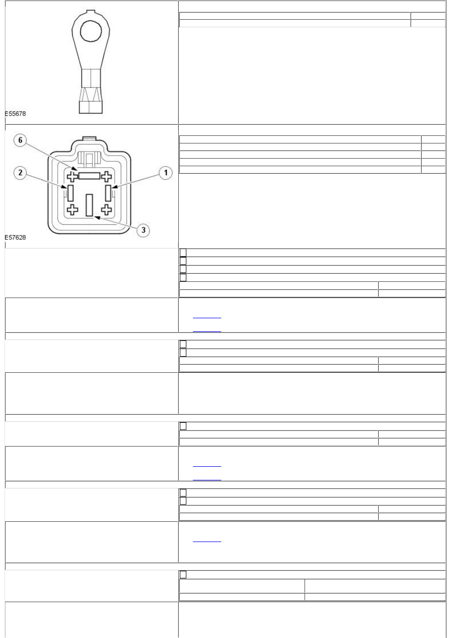
Auxiliary heater connector
Circuit
Pin
Auxiliary heater control
01
Auxiliary heater relay connector
Circuit
Pin
Auxiliary heater relay control
02
Permanent 12 volt supply
03
ECM relay controlled 12 volt supply
01
Auxiliary heater relay output
05
Key off.
Auxiliary heater fuse removed.
Key on, engine off.
Measure the resistance between:
Auxiliary heater fuse connector, harness side
Vehicle battery
Auxiliary heater control, pin 02
Positive post
Is the resistance greater than 10 ohms?
Yes
GO to C3
.
No
GO to C2
.
C2: CHECK WHETHER THE SHORT CIRCUIT TO POWER IS IN THE HARNESS OR THE AUXILIARY HEATER
Auxiliary heater connector disconnected.
Measure the resistance between:
Auxiliary heater fuse connector, harness side
Vehicle battery
Auxiliary heater control, pin 02
Positive post
Is the resistance greater than 10 ohms?
Yes
SUSPECT:- Auxiliary heater assembly
No
REPAIR the short circuit. For additional information, refer to the wiring
diagrams.
C3: CHECK THE AUXILIARY HEATER CIRCUIT CONTINUITY
Measure the resistance between:
Auxiliary heater fuse connector, harness side
Vehicle battery
Auxiliary heater control, pin 02
Negative post
Is the resistance between 0.5 ohms and 10 ohms?
Yes
GO to C6
.
No
GO to C4
.
C4: CHECK THE AUXILIARY HEATER CIRCUIT FOR SHORT CIRCUIT TO GROUND
Auxiliary heater connector disconnected.
Measure the resistance between:
Auxiliary heater fuse connector, harness side
Vehicle battery
Auxiliary heater control, pin 02
Negative post
Is the resistance greater than 10 ohms?
Yes
GO to C5
.
No
REPAIR the short circuit. For additional information, refer to the wiring
diagrams.
C5: CHECK THE AUXILIARY HEATER CIRCUIT(S) FOR OPEN CIRCUIT IN THE HARNESS
Measure the resistance between:
Auxiliary heater connector, harness
side
Auxiliary heater fuse connector, harness
side
Auxiliary heater control, pin 01
Auxiliary heater control, pin 02
Is the resistance less than 10 ohms?
Yes
SUSPECT:- Auxiliary heater assembly- Auxiliary heater assembly ground
No
REPAIR the open circuit. For additional information, refer to the wiring