Isuzu Trooper (1998-2002 year). Manual - part 640
6E–208
4JX1–TC ENGINE DRIVEABILITY AND EMISSIONS
Installation Procedure
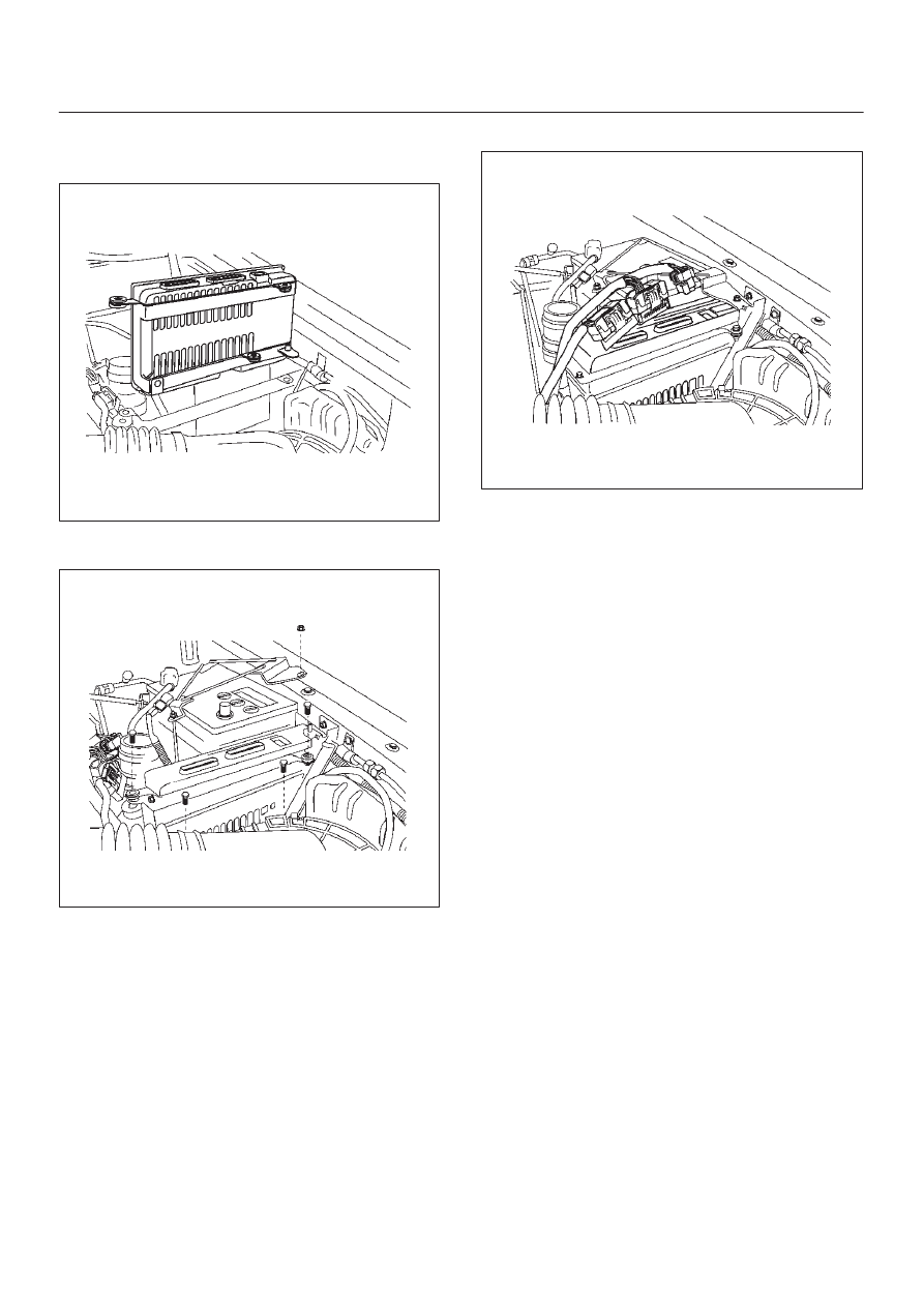
1. Install the ECM.
035RW092
2. Install the bolts, ECM bracket and battery bracket.
035RW094
3. Connect the ECM connector.
035RW093
4. Connect the negative battery cable.
If the ECM is replaced, the new ECM will need to be
programmed.
EEPROM
General Description
The Electronically Erasable Programmable Read Only
Memory (EEPROM) is a permanent memory that is
physically soldered within the ECM. The EEPROM
contains program and calibration information that the
ECM needs to control powertrain operation.
Functional Check
1. Perform the On-Board Diagnostic System Check.
2. Start the engine and run for one minute.
3. Scan for DTCs using the Tech 2.
Intake Throttle Position (ITP)
Sensor
Removal Procedure
1. Disconnect the negative battery cable.