Isuzu Trooper (1998-2002 year). Manual - part 641
6E–212
4JX1–TC ENGINE DRIVEABILITY AND EMISSIONS
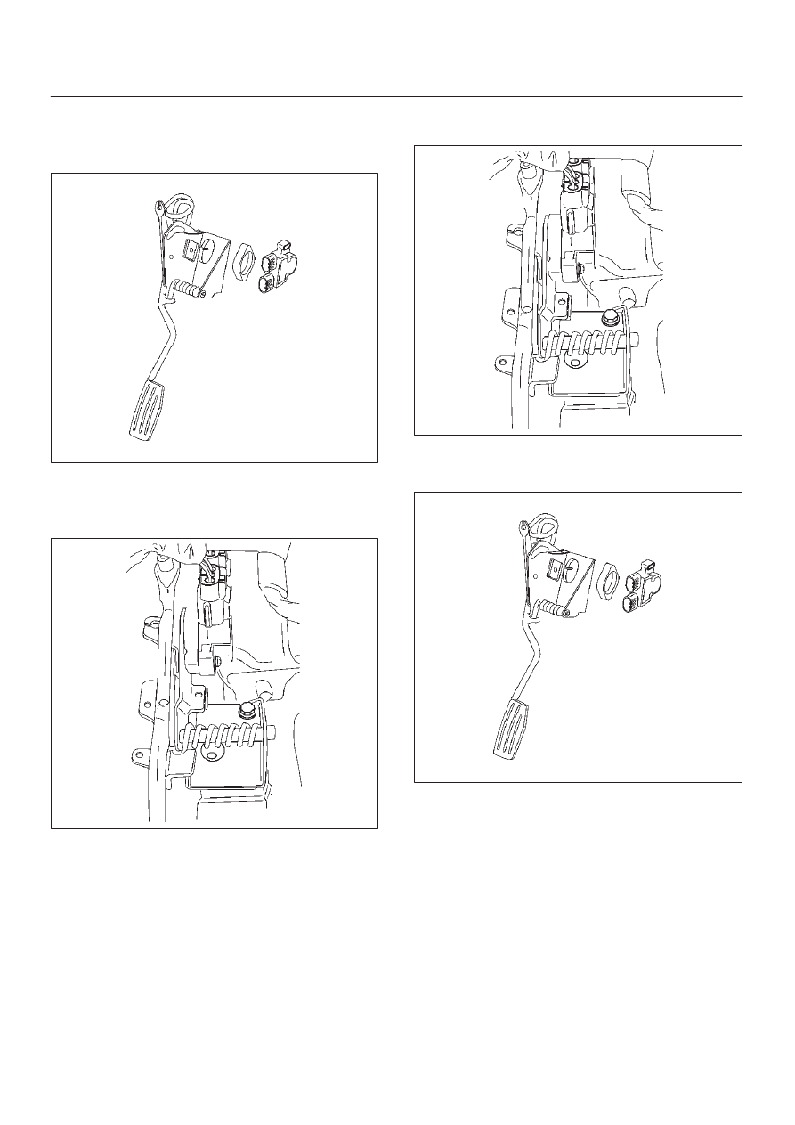
Installation Procedure
1. Install the AP sensor to the accelerator pedal
assembly.
035RW066
2. Install the accelerator pedal assembly to the
bulkhead.
3. Connect the electrical connector to the AP sensor.
035RW060
4. Connect the negative battery cable.
Accelerator Pedal Replacement
Removal Procedure
1. Disconnect the negative battery cable.
2. Disconnect the electrical connector to the AP sensor.
3. Remove the bolts and the accelerator pedal
assembly from the bulkhead.
035RW060
4. Remove the bolts and AP sensor from the accelerator
pedal assembly.
035RW066
Installation Procedure
1. Install the AP sensor to the accelerator pedal
assembly.
2. Install the accelerator pedal assembly to the
bulkhead.