Isuzu Trooper (1998-2002 year). Manual - part 566
6A – 72 ENGINE MECHANICAL
CRANK CASE
REMOVAL
1. Drain engine oil.
2. Remove transmission assembly.
3. Remove crankshaft damper pulley.
4. Remove timing belt cover, timing belt, pulley and
front plate.
5. Remove timing gear case cover.
6. Remove timing gears.
NOTE: Do not forget to set lock bolt for idle gear A and
lock pin for idle gear C.
7. Remove timing gear case.
8. Remove oil level gauge guide assembly.
9. Remove flywheel assembly.
CAUTION:
1) The flywheel heavy; be careful not to drop it.
2) Be careful no to let it slip because the hexagon
of the bolt is thin.
10. Remove rear plate (for A/T) or flywheel housing (for
MT).
11. Remove retainer.
NOTE:
1) Be careful not to damage the oil seal; it can be
reused.
2) Inspect installation portion for distortion and flow on
the slinger; also inspect for flow on the oil seal lip.
3) If there is some flow oil seal/slinger, replace a set.
12. Remove bolts from thrust plate of balance shaft LH
then remove balance shaft.
13. Loosen crank case fixing bolts.
14. Use seal cutter to take off the liquid gasket.
Seal cutter: 5-8840-2153-0
15. Remove crank case assembly.
CAUTION:
Do not give shock to crank case for prevention take
off applied vibration insulation material on the
crank case.
1
2
3
012RW029
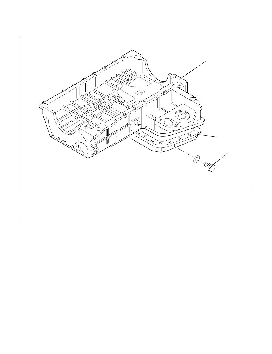
Legend
(1)
Crank Case
(2)
Oil Pan
(3)
Drain Plug